Mitsubishi Galant 9G. Manual - part 1631


  Index      Mitsubishi     Mitsubishi Galant 9G - service repair manual


Search            


Content   ..  1629  1630  1631  1632   ..


Mitsubishi Galant 9G. Manual - part 1631


WHEEL SPEED SENSOR

TSB Revision

ANTI-LOCK BRAKING SYSTEM (ABS)

35B-108

NOTE: Front wheel speed rotors are integrated with 
the BJ assembly of the drive shaft and cannot be dis-
assembled.
NOTE: Rear wheel speed rotors are integrated with 
the rear hub assembly and cannot be disassembled.

REMOVAL SERVICE POINT

.

<<A>> FRONT WHEEL SPEED SENSOR/REAR 
WHEEL SPEED SENSOR REMOVAL

CAUTION

Be careful when handling the projection at the tip of the 
wheel speed sensor and the toothed edge of the wheel 
speed rotor so as not to damage them by contacting other 
parts.

INSPECTION

M1352008400459

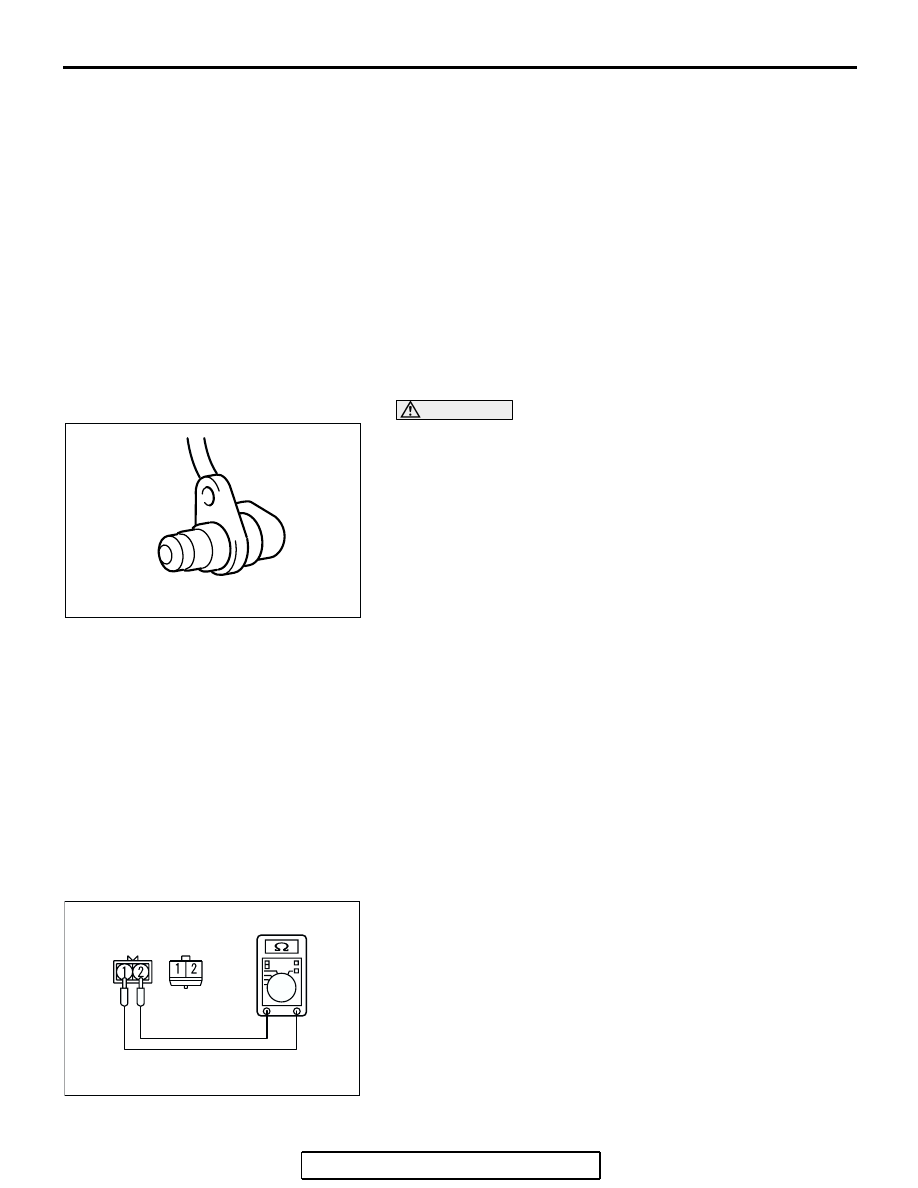
WHEEL SPEED SENSOR CHECK

1. Check whether any metallic foreign material has adhered to 

the projection at the speed sensor tip. Remove any foreign 
material. Also check whether the pole piece is damaged. 
Replace it with a new one if it is damaged.
NOTE: The projection can become magnetized due to the 
magnet inside the wheel speed sensor, causing foreign 
material to easily adhere to it. The projection may not be 
able to correctly sense the wheel rotation speed if foreign 
matter is on it or if it is damaged.

2. Measure the resistance between the wheel speed sensor 

terminals.

Standard value: 1.24 

 1.64 k

3. If the internal resistance of the wheel speed sensor is not 

within the standard value, replace it with a new wheel speed 
sensor.

FRONT WHEEL SPEED SENSOR 
REMOVAL STEPS

SPLASH SHIELD (REFER TO 
GROUP 42, FENDER 

P.42-10

).

<<A>>

1.

FRONT WHEEL  SPEED SENSOR

2.

FRONT WHEEL  SPEED ROTOR 
(REFER TO GROUP 26, 
DRIVESHAFT ASSEMBLY 

P.26-13

).

REAR WHEEL SPEED SENSOR 
REMOVAL STEPS

<<A>>

3.

REAR WHEEL  SPEED SENSOR

4.

REAR WHEEL  SPEED ROTOR 
(REFER TO GROUP 27, REAR 
AXLE HUB ASSEMBLY 

P.27-6

).

AC211046AB

AC211047AB

<REAR>

<FRONT>

SPECIFICATIONS

TSB Revision

ANTI-LOCK BRAKING SYSTEM (ABS)

35B-109

4. Remove all connections from the wheel speed sensor. The 

circuit should be open between terminals (1) and (2) and the 
body of the wheel speed sensor. If the circuit is not open, 
replace with a new wheel speed sensor.

5. Check the wheel speed sensor cable for breakage, damage 

or disconnection. Replace with a new one if a problem is 
found.
NOTE: When checking for cable damage, remove the cable 
clamp part from the body and then gently bend and pull the 
cable near the clamp.

TOOTHED WHEEL  SPEED ROTOR  CHECK

Check whether the wheel speed rotor teeth are broken or 
deformed. Replace the BJ assembly of the drive shaft, or the 
rear hub assembly, respectively, if the teeth are damaged or 
deformed.

SPECIFICATIONS

FASTENER TIGHTENING SPECIFICATION

M1352012400377

GENERAL SPECIFICATIONS

M1352000200075

SERVICE SPECIFICATION

M1352000300599

ACX01120 AB

AC000965

ITEM

SPECIFICATION

Brake tube flare nut

15 

± 2 N⋅m (12 ± 1 ft-lb)

ITEM

SPECIFICATION

ABS control method

4-sensor, 4-channel

Numbers of wheel speed 
rotor teeth

Front

43

Rear

43

Wheel speed sensor

Type

Magnet coil type

Gap between sensor and rotor mm (in)

0.2 

− 0.5 (0.008 − 0.020)

<Non-adjustable type>

ITEM

STANDARD VALUE

Wheel speed sensor internal resistance k

1.24 

− 1.64

NOTES

TSB Revision

1

ALPHABETICAL INDEX

A

A/C Switch.........................................................................

55A-266

A/C system........................................................................

13A-1081

A/C system........................................................................

13B-1134

A/T Control Component.....................................................

23A-364

A/T Faulty Operation Prevention Mechanism

Diagnosis .......................................................................

23A-353

A/T Key Interlock and Shift Lock Mechanism....................

23A-385

ABS

Actuator Test..................................................................

35B-94

ECU, Check at Terminal ................................................

35B-95

Accelerator Pedal..............................................................

17-9

Accessory Socket..............................................................

54A-131

Accessory Socket

Circuit Diagram ..............................................................

90-202

Adhesive

Automatic Transaxle......................................................

23B-90

Body ..............................................................................

42-85

Engine <3.8L Engine> ...................................................

11C-58

Engine <2.4L Engine> ...................................................

11A-68

Engine Cooling ..............................................................

14-28

Engine Lubrication.........................................................

12-7

Engine Overhaul <2.4L Engine> ...................................

11B-73

Engine Overhaul <3.8L Engine> ...................................

11D-65

Exterior ..........................................................................

51-45

Intake and Exhaust........................................................

15-24

MFI <2.4L Engine> ........................................................

13A-1142

MFI <3.8L Engine> ........................................................

13B-1193

Steering .........................................................................

37-67

Adhesive Table..................................................................

00-68

Air Bag Module

Disposal Procedures .....................................................

52B-388

Air Bag Module(s)..............................................................

52B-369

Air Cleaner........................................................................

15-4

Air Cleaner Element

Replace .........................................................................

00-43

Air Conditioning

Actuator Test..................................................................

55A-252

Automatic, Circuit Diagram ............................................

90-28

Charging........................................................................

55A-260

Compressor Drive Belt Adjustment ...............................

55A-260

Compressor Noise Check..............................................

55A-262

Condenser and Condenser Fan Motor ..........................

55A-283

ECU Terminal Check .....................................................

55B-22

ECU Terminal Check

LOW TYPE................................................................

55A-253

MIDDLE TYPE...........................................................

55A-255

Idle-up Operation Check ................................................

55A-264

Manual, Circuit Diagram

LOW...........................................................................

90-152

MIDDLE.....................................................................

90-162

Outside Air Temperature Sensor ...................................

55A-276

Performance Test ..........................................................

55A-261

Power Relay Check .......................................................

55A-263

Refrigerant Leak Repair ................................................

55A-262

Refrigerant Line .............................................................

55A-285

Sensors (Full-auto A/C) .................................................

55B-25

Sight Glass Refrigerant Level Test ................................

55A-259

Amplifier ............................................................................

54A-210

Antenna.............................................................................

54A-212

Anti-Lock Braking System (ABS)

Circuit Diagram

VEHICLES WITH TRACTION CONTROL (TCL).......

90-230

VEHICLES WITHOUT TRACTION CONTROL (TCL)

90-224

Diagnosis .......................................................................

35B-4

Audio System

Circuit Diagram

VEHICLES WITH AUDIO AMPLIFIER ......................

90-196

VEHICLES WITHOUT AUDIO AMPLIFIER...............

90-192

Auto A/C

Diagnosis.......................................................................

55B-4

Auto-cruise Control............................................................

17-9

Auto-cruise Control............................................................

17-74

Auto-cruise Control Switch

Check.............................................................................

17-71

Auto-cruise Control System

Circuit Diagram..............................................................

90-216

Component Check.........................................................

17-73

Diagnosis.......................................................................

17-10

Automatic Transaxle

A/T Key Interlock and Shift Lock Mechanism................

23A-385

Adhesive........................................................................

23B-90

Adjusting Plate, Snap Ring and Spacers .......................

23B-88

Diagnosis.......................................................................

23A-14

Fluid Level Check ..........................................................

00-53

Sealant...........................................................................

23B-90

Transaxle Assembly.......................................................

23A-387

Transaxle Control...........................................................

23A-380

Valve Body Spring Identification ....................................

23B-87

Automatic Transaxle Control Component

Check.............................................................................

23A-374

Automatic Transaxle Fluid

Level Check ...................................................................

00-53

Auto-tensioner

Check.............................................................................

11A-8

B

Backup Light

Circuit Diagram..............................................................

90-120

Ball Joint Dust Cover

Inspection <Rear suspension>......................................

34-8

Inspection <Front suspension>......................................

33-8

Replacement <Rear suspension> .................................

34-15

Replacement <Front suspension>.................................

33-17

Ball Joint Dust Cover Inspection

Steering..........................................................................

37-24

Ball Joint Seals

Check.............................................................................

00-59

Barometric Pressure Sensor

Check.............................................................................

17-88

Basic Brake System

Diagnosis.......................................................................

35A-3

Battery

Charging ........................................................................

54A-6

Check.............................................................................

54A-5

Handling.........................................................................

00E-12

Remedy for a Discharged Battery..................................

35B-104

Test................................................................................

54A-6

Belt, Timing

Replace..........................................................................

00-45

BJ Boot

Replacement..................................................................

26-26

Bleeding

Brakes (Basic) ...............................................................

35A-16

Power Steering ..............................................................

37-21

Blower................................................................................

55A-272

Blower Assembly ...............................................................

55A-269

Blower Assembly ...............................................................

55A-267

Body

Adhesive........................................................................

42-85

Diagnosis.......................................................................

42-4

Sealant...........................................................................

42-85

Boots

Driveshaft, Check ..........................................................

00-59

Brake Booster ....................................................................

35A-26

Brake Booster

Operating Check............................................................

35A-14

Removal and Installation ...............................................

35A-26


Content   ..  1629  1630  1631  1632   ..