Mitsubishi Galant 9G. Manual - part 1630


  Index      Mitsubishi     Mitsubishi Galant 9G - service repair manual


Search            


Content   ..  1628  1629  1630  1631   ..


Mitsubishi Galant 9G. Manual - part 1630


ON-VEHICLE SERVICE

TSB Revision

ANTI-LOCK BRAKING SYSTEM (ABS)

35B-104

12.After inspection, disconnect scan tool MB991958 

immediately after turning the ignition switch to the "LOCK" 
(OFF) position. 

IN THE EVENT OF A DISCHARGED BATTERY

M1352003500547

WARNING

If the ABS is not operating, the vehicle will be unsta-
ble during braking, Do not drive the vehicle with the 
ABS-ECU connector disconnected or with the ABS 
not operating.

If the engine is started using a booster cable when the battery 
is completely flat, and the vehicle is then driven without waiting 
for the battery to be recharged, the engine may misfire and it 
may not be possible to drive the vehicle. This is because the 
ABS consumes a large amount of current when carrying out its 
initial checks. If this happens, recharge the battery fully.
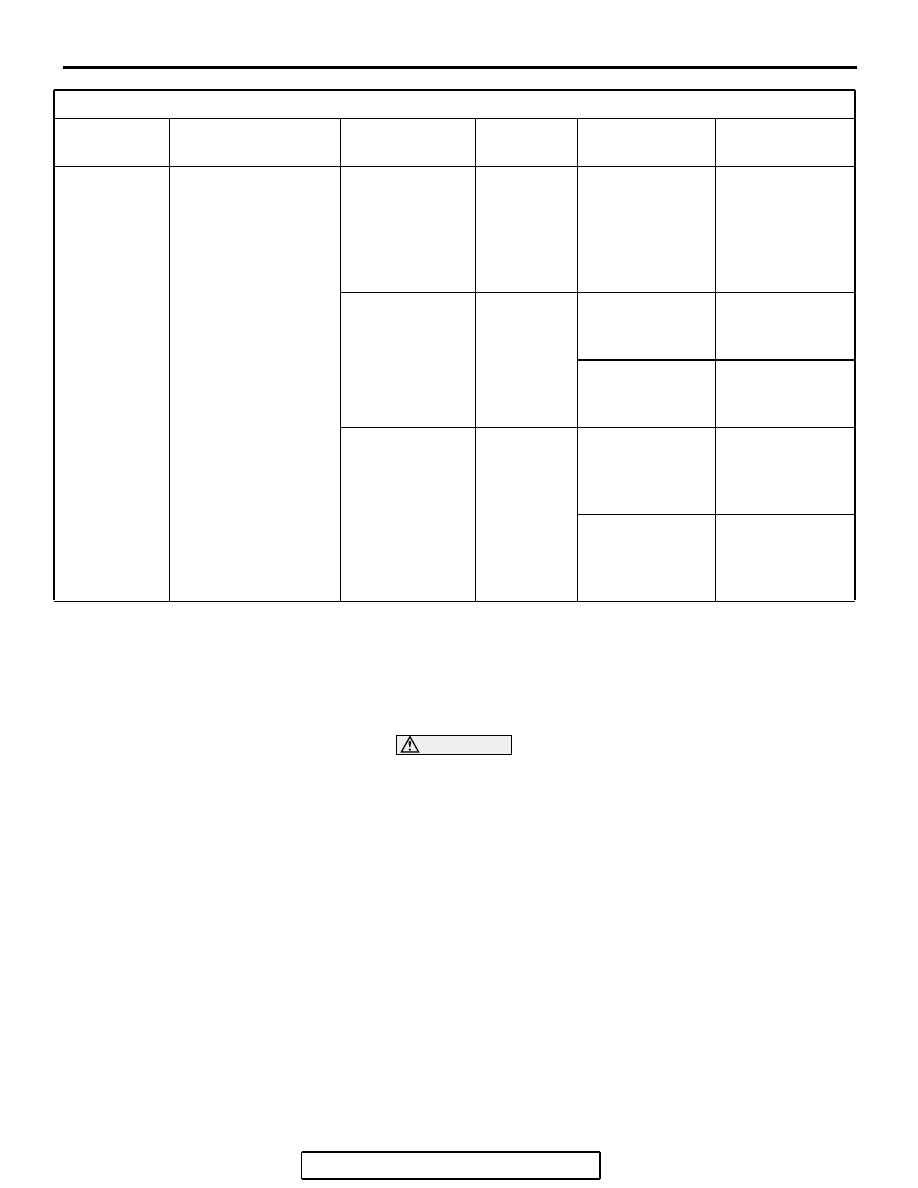
DIAGNOSIS TABLE

MUT-III 
DISPLAY

OPERATION

INSPECTION 
RESULT

JUDGMENT PROBABLE 

CAUSE

REMEDY

01 FR VALVE
02 FL VALVE
03 RR VALVE
04 RL VALVE

• Depress brake 

pedal to lock 
wheel.

• Using scan tool 

MB991958, select 
the wheel to be 
checked and force 
the actuator to 
operate.

• Turn the selected 

wheel manually to 
check the change 
of brake force.

Brake force is 
released for 
three seconds 
after wheels 
have been 
locked.

Normal

Wheel does not 
lock when brake 
pedal is 
depressed.

Abnormal

Clogged brake 
line other than 
hydraulic unit

Check and clean 
brake line

Clogged 
hydraulic circuit 
in hydraulic unit

Replace 
hydraulic unit 
assembly

Brake force is 
not released

Abnormal

Incorrect 
hydraulic unit 
brake tube 
connection

Connect correctly

Hydraulic unit 
solenoid valve 
not functioning 
correctly

Replace 
hydraulic unit 
assembly

HYDRAULIC UNIT

TSB Revision

ANTI-LOCK BRAKING SYSTEM (ABS)

35B-105

HYDRAULIC UNIT

REMOVAL AND INSTALLATION

M1352008600464

NOTE: The ABS-ECU is integrated in the hydraulic unit.

Pre-removal Operation
• Strut Tower Bar Removal (Refer to GROUP 42, Strut 

Tower Bar 

P.42-12

).

• Brake Fluid Draining

Post-installation Operation
• Brake Fluid Filling

• Brake Line Bleeding (Refer to GROUP 35A, On-vehicle 

Service 

− Bleeding 

P.35A-16

).

• Hydraulic Unit Check (Refer to 

P.35B-102

).

• Strut Tower Bar Installation (Refer to GROUP 42, Strut 

Tower Bar 

P.42-12

).

AC306183AB

15 ± 2 N·m
12 ± 1 ft-lb

4

5

2

3

1

2

3

2

REMOVAL STEPS

• POWER STEERING OIL 

RESERVOIR (REFER TO  GROUP 
37A, POWER STEERING HOSES 

P.37-58

). <3.8L ENGINE>

• HARNESS CONNECTORS 

AROUND THE ABS-ECU <3.8L 
ENGINE>

• HARNESS CLAMPS AROUND THE 

ABS-ECU <3.8L ENGINE>

• CONNECTOR BRACKETS AROUND 

THE ABS-ECU <3.8L ENGINE>

<<A>>

1. ABS-ECU HARNESS CONNECTOR

>>A<<

2. BRAKE TUBE CONNECTION
3. ABS EQUIPMENT BOLT AND NUTS

<<B>>

4. BRAKE MODULATOR HYDRAULIC 

UNIT (HYDRAULIC UNIT AND 
ABS-ECU)

5. BRAKE HYDRAULIC UNIT 

BRACKET

REMOVAL STEPS (Continued)

HYDRAULIC UNIT

TSB Revision

ANTI-LOCK BRAKING SYSTEM (ABS)

35B-106

REMOVAL SERVICE POINTS

.

<<A>> ABS-ECU HARNESS CONNECTOR DIS-
CONNECTION

Move the lock lever of the ABS-ECU connector as shown in the 
illustration, and then disconnect the harness connector.

.

<<B>>  BRAKE MODULATOR HYDRAULIC UNIT 
(HYDRAULIC UNIT AND ABS-ECU) REMOVAL

WARNING

The hydraulic unit is heavy. Use care when removing 
it.

CAUTION

• The hydraulic unit cannot be disassembled. Never 

loosen its nuts or bolts.

• Do not drop or shock the hydraulic unit.

• Do not turn the hydraulic unit upside down or lay it on 

its side.

Remove the hydraulic unit as shown, taking care not to dam-
age surrounding components such as the flexible suction hose 
<3.8L engine>.

AC304742

AB

LOCK LEVER

AC211808 AC

BRAKE MODULATOR
HYDRAULIC UNIT
(HYDRAULIC UNIT
AND ABS-ECU)

FLEXIBLE SUCTION HOSE

<3.8L ENGINE>

WHEEL SPEED SENSOR

TSB Revision

ANTI-LOCK BRAKING SYSTEM (ABS)

35B-107

INSTALLATION SERVICE POINT

.

>>A<< BRAKE TUBE CONNECTION

Connect the tubes to the hydraulic unit assembly as shown in 
the illustration.

1. To the front brake (LH)
2. To the rear brake (RH)
3. To the rear brake (LH)
4. To the front brake (RH)
5. From the master cylinder (secondary)
6. From the master cylinder (primary)

WHEEL SPEED SENSOR

REMOVAL AND INSTALLATION

M1352008300548

AC210718AC

6

5

2

3

1

4

Post-installation Operation
• Wheel Speed Sensor Output Voltage Measurement 

(Refer to 

P.35B-100

).

AC306191AB

<FRONT>

<REAR>

1

2

4

3

4

<RH>

<LH>


Content   ..  1628  1629  1630  1631   ..