Mitsubishi Galant 9G. Manual - part 1628


  Index      Mitsubishi     Mitsubishi Galant 9G - service repair manual


Search            


Content   ..  1626  1627  1628  1629   ..


Mitsubishi Galant 9G. Manual - part 1628


ANTI-LOCK BRAKING SYSTEM (ABS) DIAGNOSIS

TSB Revision

ANTI-LOCK BRAKING SYSTEM (ABS)

35B-96

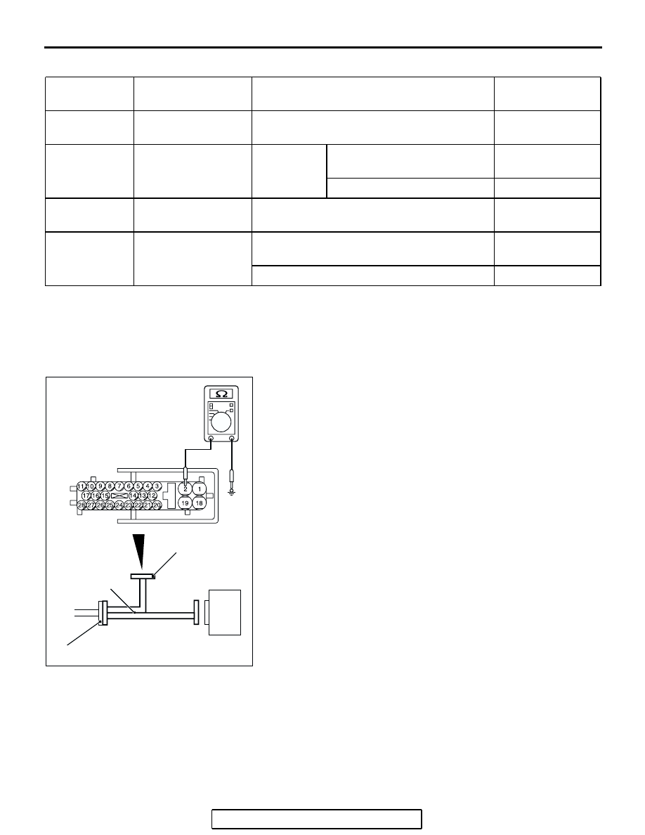
2. The terminal layouts are shown in the illustrations below.

.

RESISTANCE AND CONTINUITY BETWEEN 
HARNESS-SIDE CONNECTOR TERMINALS

Required Special Tool:
MB991970: ABS Check Harness
1. Turn the ignition switch to the "LOCK" (OFF) position and 

disconnect the ABS-ECU connectors before checking 
resistance and continuity.

2. Check the resistance and continuity between the terminals 

indicated in the table below.

3. The terminal layout is shown in the illustration.

CONNECTOR 
TERMINAL NO

SIGNAL

CHECKING REQUIREMENT

NORMAL 
CONDITION

1

Solenoid valve power 
supply

Always

Battery positive 
voltage

3

Stop light switch input Ignition 

switch: "ON" 

Stop light switch: "ON" 

Battery positive 
voltage

Stop light switch: "OFF" 

Approximately 0 V

19

Motor power supply

Always

Battery positive 
voltage

20

ABS-ECU power 
supply

Ignition switch: "ON" 

Battery positive 
voltage

Ignition switch: "START" 

Approximately 0 V

AC211160 AC

ABS-ECU

A-02 HARNESS CONNECTOR

MB991970

INSPECTION
HARNESS
CONNECTOR

ANTI-LOCK BRAKING SYSTEM (ABS) DIAGNOSIS

TSB Revision

ANTI-LOCK BRAKING SYSTEM (ABS)

35B-97

CONNECTOR TERMINAL NO.

SIGNAL

NORMAL CONDITION

− 10

Front-right wheel speed sensor

1.24 

− 1.64 kΩ

11 

− 17

Rear-right wheel speed sensor

1.24 

− 1.64 kΩ

16 

− 26

Front-left wheel speed sensor

1.24 

− 1.64 kΩ

27 

− 28

Rear-left wheel speed sensor

1.24 

− 1.64 kΩ

− body ground

Ground

Less than 2 ohms

18 

− body ground

Ground

Less than 2 ohms

SPECIAL TOOLS

TSB Revision

ANTI-LOCK BRAKING SYSTEM (ABS)

35B-98

SPECIAL TOOLS

M1352000600653

TOOL

TOOL NUMBER AND NAME SUPERSESSION

APPLICATION

MB991958

A: MB991824
B: MB991827
C: MB991910
D: MB991911
E: MB991914
F: MB991825
G: MB991826

MUT-III Sub Assembly

A: Vehicle Communication 

Interface (V.C.I.)

B: MUT-III USB Cable
C: MUT-III Main Harness A 

(Vehicles with CAN 
communication system)

D: MUT-III Main Harness B 

(Vehicles without CAN 
communication system)

E: MUT-III Main Harness C 

(for Daimler Chrysler 
models only)

F: MUT-III Adapter Harness
G: MUT-III Trigger Harness

MB991824

−KIT

NOTE: G: MB991826 
MUT-III Trigger 
Harness is not 
necessary when 
pushing V.C.I. ENTER 
key.

Checking diagnostic 
trouble codes

CAUTION

For vehicles with CAN 
communication, use 
MUT-III main harness A 
to send simulated 
vehicle speed. If you 
connect MUT-III main 
harness B instead, the 
CAN communication 
does not function 
correctly.

MB991970 
ABS check harness

ABS-ECU terminal 
voltage measurement

MB991910

MB991826

MB991958

MB991911

MB991914

MB991824

MB991827

MB991825

DO NOT USE

A

B

C

D

E

F

G

DO NOT USE

MB991970

SPECIAL TOOLS

TSB Revision

ANTI-LOCK BRAKING SYSTEM (ABS)

35B-99

MB991223 
Harness set
 A: MB991219
 Inspection harness

General service tools

Wheel speed sensor 
output voltage 
measurement

TOOL

TOOL NUMBER AND NAME SUPERSESSION

APPLICATION

MB991223

A

AH


Content   ..  1626  1627  1628  1629   ..