Mitsubishi Galant 9G. Manual - part 1629


  Index      Mitsubishi     Mitsubishi Galant 9G - service repair manual


Search            


Content   ..  1627  1628  1629  1630   ..


Mitsubishi Galant 9G. Manual - part 1629


ON-VEHICLE SERVICE

TSB Revision

ANTI-LOCK BRAKING SYSTEM (ABS)

35B-100

ON-VEHICLE SERVICE

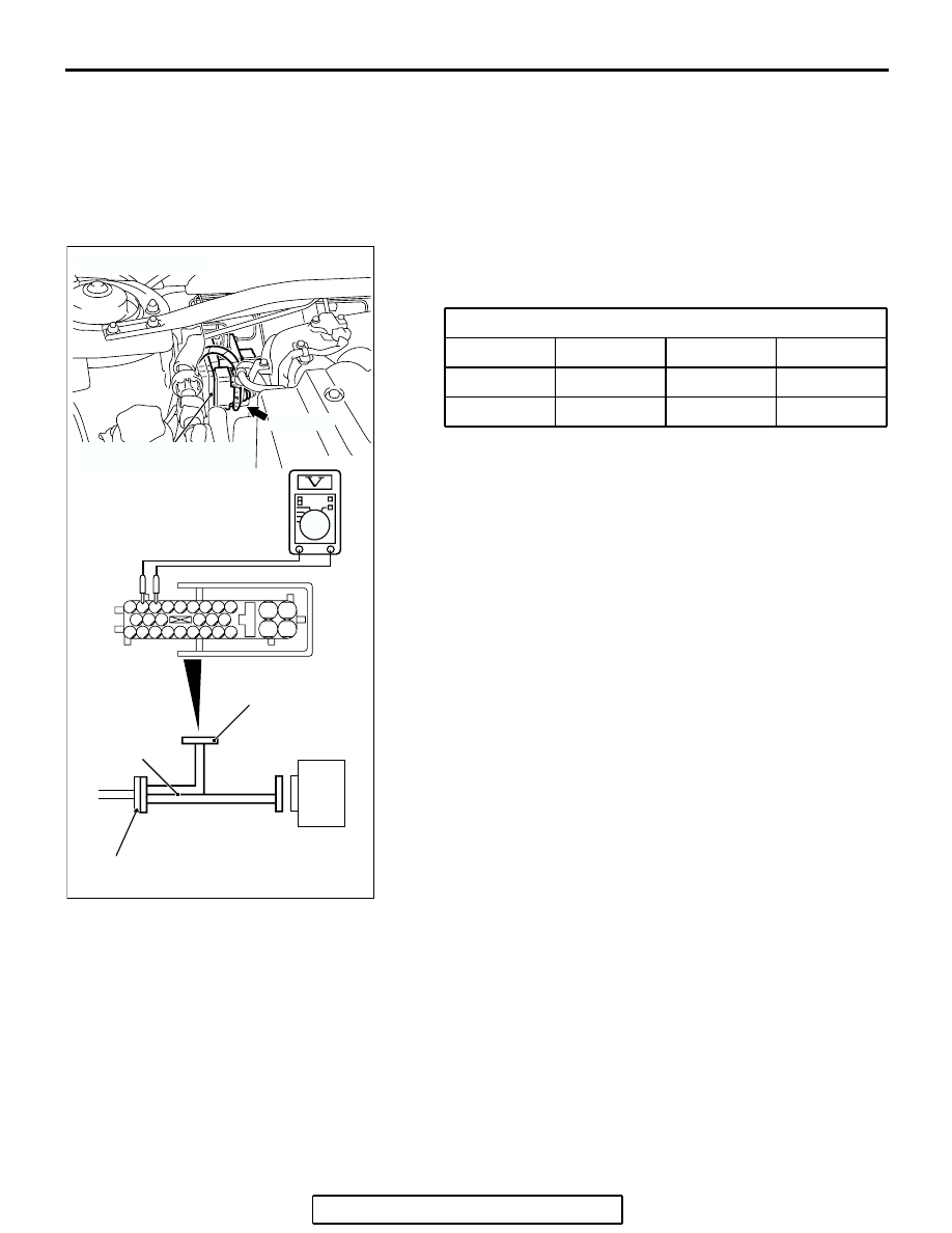
WHEEL SPEED SENSOR OUTPUT VOLTAGE 
MEASUREMENT

M1352001600667

Required Special Tool:
MB991219: Inspection Harness
1. Release the parking brake and lift up the vehicle.
2. Disconnect the ABS-ECU connector A-02, and then use 

special tool MB991219 to measure the output voltage at the 
harness side connector.

TERMINAL NO.

Front left

Front right

Rear left

Rear right

16

9

27

11

26

10

28

17

AC306403

19

2

18

1

8

9

7

6

5

4

3

10

11   

25

15

16

17

27

28

26

12

13

14

23

24

22 21 20

AK

ABS-ECU

MB991970

CHECK CONNECTOR

A-02 HARNESS
CONNECTOR

A-02 (GR)

CONNECTOR: A-02

HYDRAULIC UNIT
(WITH BUILT-IN ABS-ECU)

ON-VEHICLE SERVICE

TSB Revision

ANTI-LOCK BRAKING SYSTEM (ABS)

35B-101

3. Manually turn the wheel to be measured 1/2 to 1 

turn/second. Measure the output voltage with a voltmeter or 
oscilloscope.
NOTE: Check the connection of the sensor harness and 
connector before using the oscilloscope.

Output voltage:

• Minimal voltmeter reading: 42 mV

• Maximum voltmeter reading: 300 mV

• Minimal oscilloscope reading: 120 mV

• Maximum oscilloscope reading: 600 mV

Probable causes of low output voltage

• Wheel speed sensor pole piece to wheel speed rotor clear-

ance too large

• Faulty wheel speed sensor

4. To observe the waveform with an oscilloscope:

• Front Wheels: Shift into "D" range and drive the wheels.

• Rear Wheels: Turn the wheels manually at a constant 

speed

NOTE: The output waveform is low when the wheel speed is 
low. Similarly, it will be higher as the wheel speed increases. 
Waveform may also be observed by driving the vehicle.

.

POINTS IN WAVEFORM MEASUREMENT

NOTE: The wheel speed sensor cable moves in relation to motion of the front or rear suspension. Therefore, 
it is likely that it has an open circuit only when driving on rough roads but it functions normally when driving on 
smooth roads. It is recommended to observe sensor output voltage waveform also under special conditions, 
such as driving on a rough road.

AC000949 AC

WHEN TURNED MANUALLY

IN "D" RANGE, IDLING
[5 

− 6 km/h (3 − 4 mph)]

[10.0 ms/DIV 1 V/DIV]

[10.0 ms/DIV 1 V/DIV]

SYMPTOM

PROBABLE CAUSE

REMEDY

Too small or zero waveform 
amplitude

Faulty wheel speed sensor or 
excessive gap between it and the 
wheel speed rotor

Replace wheel speed sensor

Waveform amplitude fluctuates 
excessively (This is no problem if 
the minimum amplitude is 100 mV 
or more)

Axle hub eccentric or with large 
runout

Replace hub assembly

Faulty ABS-ECU ground

Repair harness wires

Noisy or disturbed waveform

Open circuit in wheel speed sensor Replace wheel speed sensor
Open circuit in harness

Repair harness wire

Incorrectly mounted wheel speed 
sensor

Mount wheel speed sensor 
correctly

Wheel speed rotor with missing or 
damaged teeth

Replace wheel speed rotor

ON-VEHICLE SERVICE

TSB Revision

ANTI-LOCK BRAKING SYSTEM (ABS)

35B-102

HYDRAULIC UNIT CHECK

M1352001700512

Required Special Tools:

• MB991958: MUT-III Sub Assembly

• MB991824: Vehicle Communication Interface (V.C.I.)

• MB991827: MUT-III USB Cable

• MB991910: MUT-III Main Harness A (Vehicles with CAN 

communication system)

CAUTION

• The roller of the braking force tester and the tire should 

be dry during testing.

• When testing the front brakes, apply the parking brake. 

When testing the rear brakes, stop the front wheels 
with chocks.

1. Jack up the vehicle. Then support the vehicle with rigid 

racks at the specified jack-up points or place the front or rear 
wheels on the rollers of the braking force tester.

2. Release the parking brake, and feel the drag force (drag 

torque) on each road wheel. When using the braking force 
tester, take a reading of the brake drag force.

CAUTION

To prevent damage to scan tool MB991958, always turn the 
ignition switch to the "LOCK" (OFF) position before con-
necting or disconnecting scan tool MB991958.
3. Connect scan tool MB991958 to the data link connector.
4. After checking that the selector lever is in "P" range, start the 

engine.

5. Select "Interactive Diagnosis" from the start-up screen.
6. Select "System Select."
7. Choose "ABS" from the "CHASSIS" tab.
8. Select "Actuator Test" from "ABS" screen
9. Choose an appropriate item for hydraulic unit check.

NOTE: The ABS system will switch to the scan tool mode 
and the ABS warning light will illuminate.
NOTE: When the ABS has been interrupted by the fail-safe 
function, scan tool MB991958 actuator testing cannot be 
used.

AC305412

AB

MB991910

DATA LINK

CONNECTOR

MB991824

MB991827

ON-VEHICLE SERVICE

TSB Revision

ANTI-LOCK BRAKING SYSTEM (ABS)

35B-103

10.Turn the wheel by hand and check the change in braking 

force when the brake pedal is depressed. When using the 
braking force tester, depress the brake pedal until the 
braking force is at the following values, and check that the 
braking force changes to the brake drag force reading taken 
in step 2 when the actuator is force-driven. The result should 
be as shown in the diagram above.

11.If the result of inspection is abnormal, repair according to the 

Diagnosis Table below.

Front wheel

785 

− 981 N (176 − 220 lb.)

Rear wheel

588 

− 784 N (132 − 176 lb.)

AC000954AB

SCAN TOOL ACTUATOR TEST
(ITEM NO.01, 02, 03, 04) START

1 s

2 s

3 s

DEPRESSED

RELEASED

PRESSURE INCREASE

PRESSURE DECREASE

PRESSURE HOLD

LOCK

DRAG FORCE
WHEN THE
PEDAL IS FREE

PEDAL
OPERATION

SOLENOID
VALVE
POSITION

CHECKING
THE BRAKE
FORCE


Content   ..  1627  1628  1629  1630   ..