Mitsubishi Galant 9G. Manual - part 1621


  Index      Mitsubishi     Mitsubishi Galant 9G - service repair manual


Search            


Content   ..  1619  1620  1621  1622   ..


Mitsubishi Galant 9G. Manual - part 1621


ANTI-LOCK BRAKING SYSTEM (ABS) DIAGNOSIS

TSB Revision

ANTI-LOCK BRAKING SYSTEM (ABS)

35B-68

Q: Is intermediate connector A-13 and C-29, brake fluid 

level switch connector B-07, joint connector C-01, 
combination meter connector C-101 and parking brake 
switch connector C-18 damaged?
YES : 
Repair or replace the damaged component(s). Refer 

to GROUP 00E, Harness Connector Inspection 

P.00E-2

. Then go to Step 11.

NO :  Go to Step 8.

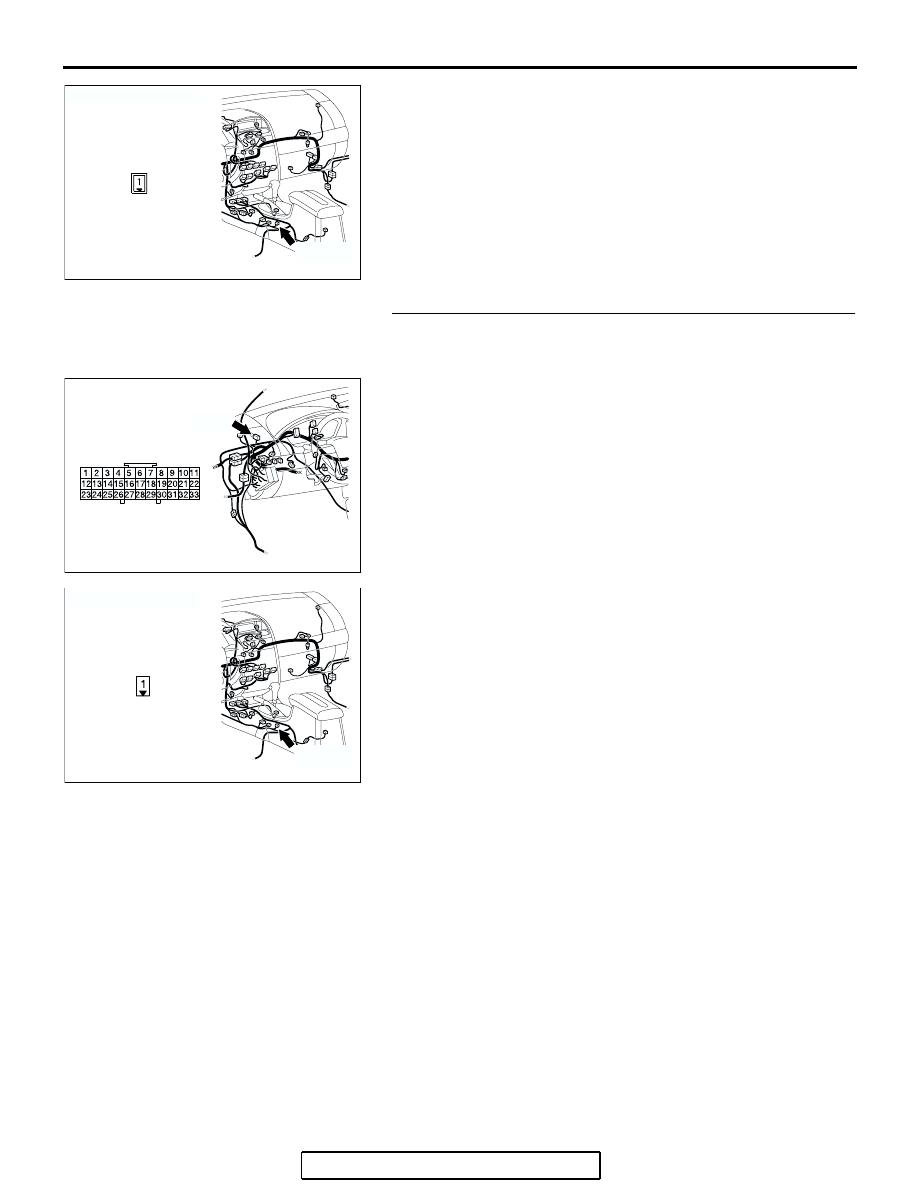
STEP 8. Check the harness wires between joint connector 
C-01 (terminal 28) and parking brake switch connector 
C-18 (terminal 1).
Q: Is the harness wires between joint connector C-01 

(terminal 28) and parking brake switch connector C-18 
(terminal 1) damaged?
YES : 
Repair the wiring harness. Then go to Step 11.
NO :  Go to Step 9.

AC305233

CONNECTOR: C-18

CT

C-18 (B)

C-18 HARNESS
CONNECTOR

AC305231

CONNECTOR: C-01

DH

C-01

AC305233

CONNECTOR: C-18

CU

C-18 (B)

C-18 HARNESS
CONNECTOR
(HARNESS SIDE)

ANTI-LOCK BRAKING SYSTEM (ABS) DIAGNOSIS

TSB Revision

ANTI-LOCK BRAKING SYSTEM (ABS)

35B-69

STEP 9. Check the harness wires between brake fluid level 
switch connector B-07 (terminal 1) and joint connector 
C-01 (terminal 27).
Q: Is the harness wires between brake fluid level switch 

connector B-07 (terminal 1) and joint connector C-01 
(terminal 27) damaged?
YES : 
Repair the wiring harness. Then go to Step 11.
NO :  Go to Step 10.

STEP 10. Check the harness wires between joint connector 
C-01 (terminal 26) and combination meter connector C-101 
(terminal 7).
Q: Is the harness wires between joint connector C-01 

(terminal 26) and combination meter connector C-101 
(terminal 7) damaged?
YES : 
Repair the wiring harness. Then go to Step 11.
NO :  Go to Step 11.

AC305229AI

B-07 (GR)

CONNECTOR: B-07

C-18 HARNESS
CONNECTOR
(HARNESS SIDE)

AC305231

CONNECTOR: C-01

DH

C-01

AC305231

CONNECTOR: C-01

DH

C-01

AC305231

CONNECTOR: C-101

DJ

C-101

C-101 HARNESS
CONNECTOR
(HARNESS SIDE)

ANTI-LOCK BRAKING SYSTEM (ABS) DIAGNOSIS

TSB Revision

ANTI-LOCK BRAKING SYSTEM (ABS)

35B-70

STEP 11. Recheck for diagnostic trouble code.
Check again if the DTC is set.
(1) Turn the ignition switch to the "ON" position.
(2) Erase the DTC.
(3) Turn the ignition switch to the "LOCK" (OFF) position.
(4) Turn the ignition switch to the "ON" position.
(5) Check if the DTC is set.
(6) Turn the ignition switch to the "LOCK" (OFF) position.
Q: Is DTC C1395 set?

YES : Replace the combination meter (integrated with meter 

ECU). Then go to Step 12     .

NO :  It can be assumed that this malfunction is intermittent. 

Refer to GROUP 00, How to Use 
Troubleshooting/Inspection Service Points 

− How to 

Cope with Intermittent Malfunction 

P.00-14

.

STEP 12. Recheck for diagnostic trouble code.
Check again if the DTC is set.
(1) Turn the ignition switch to the "ON" position.
(2) Erase the DTC.
(3) Turn the ignition switch to the "LOCK" (OFF) position.
(4) Turn the ignition switch to the "ON" position.
(5) Check if the DTC is set.
(6) Turn the ignition switch to the "LOCK" (OFF) position.
Q: Is DTC C1395 set?

YES : Go to Step 1.
NO :  The procedure is complete.

AC305412

AB

MB991910

DATA LINK

CONNECTOR

MB991824

MB991827

AC305412

AB

MB991910

DATA LINK

CONNECTOR

MB991824

MB991827

ANTI-LOCK BRAKING SYSTEM (ABS) DIAGNOSIS

TSB Revision

ANTI-LOCK BRAKING SYSTEM (ABS)

35B-71

DTC C1607: Trouble in ABS-ECU

CAUTION

If there is any problem in the CAN bus lines, an 
incorrect diagnostic trouble code may be set. 
Prior to this diagnosis, diagnose the CAN bus 
lines.

CAUTION

Whenever the ECU is replaced, ensure that the 
CAN bus lines are normal.

.

ABS DTC SET CONDITIONS

The ABS-ECU always monitors itself while the sys-
tem is working. If the ECU detects any faults, it will 
set this DTC.

.

TROUBLESHOOTING HINTS (The most 
likely causes for these DTCs are to set 
are:)

• Malfunction of the hydraulic unit (integrated with 

ABS-ECU)

.

DIAGNOSIS

Required Special Tools:

• MB991958: Scan Tool (MUT-III Sub Assembly)

• MB991824: Vehicle Communication Interface (V.C.I.)

• MB991827: MUT-III USB Cable

• MB991910: MUT-III Main Harness A

STEP 1. Using scan tool MB991958, diagnose the CAN bus 
line.

CAUTION

To prevent damage to scan tool MB991958, always turn the 
ignition switch to the "LOCK" (OFF) position before con-
necting or disconnecting scan tool MB991958.
(1) Connect scan tool MB991958 to the data link connector.
(2) Turn the ignition switch to the "ON" position.
(3) Diagnose the CAN bus line.
(4) Turn the ignition switch to the "LOCK" (OFF) position.
Q: Is the CAN bus line found to be normal?

YES : Go to Step 2.
NO :  Repair the CAN bus line (Refer to GROUP 54C, 

Diagnosis 

P.54C-14

).  Then go to Step 2.

AC305412

AB

MB991910

DATA LINK

CONNECTOR

MB991824

MB991827


Content   ..  1619  1620  1621  1622   ..