Content .. 1620 1621 1622 1623 ..
Mitsubishi Galant 9G. Manual - part 1622
ANTI-LOCK BRAKING SYSTEM (ABS) DIAGNOSIS
TSB Revision
ANTI-LOCK BRAKING SYSTEM (ABS)
35B-72
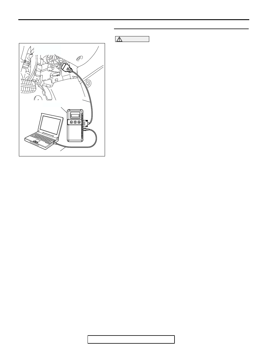
STEP 2. Recheck for diagnostic trouble code.
CAUTION
To prevent damage to scan tool MB991958, always turn the
ignition switch to the "LOCK" (OFF) position before con-
necting or disconnecting scan tool MB991958.
(1) Turn the ignition switch to the "ON" position.
(2) Erase the DTC.
(3) Turn the ignition switch to the "LOCK" (OFF) position.
(4) Turn the ignition switch to the "ON" position.
(5) Check if the DTC is set.
(6) Turn the ignition switch to the "LOCK" (OFF) position.
Q: Is DTC C1607 set?
YES : Replace the hydraulic unit (integrated with
ABS-ECU).
NO : The procedure is complete.
AC305412
AB
MB991910
DATA LINK
CONNECTOR
MB991824
MB991827