Mitsubishi Galant 9G. Manual - part 1518


  Index      Mitsubishi     Mitsubishi Galant 9G - service repair manual


Search            


Content   ..  1516  1517  1518  1519   ..


Mitsubishi Galant 9G. Manual - part 1518


ON-VEHICLE SERVICE

TSB Revision

POWER STEERING

37-22

CAUTION

If the fluid level rises suddenly after the engine is stopped, 
the air has not been completely bled. If air bleeding is not 
complete, there will be abnormal noises from the pump 
and the flow-control valve, and this condition could reduce 
the life of the power steering components.
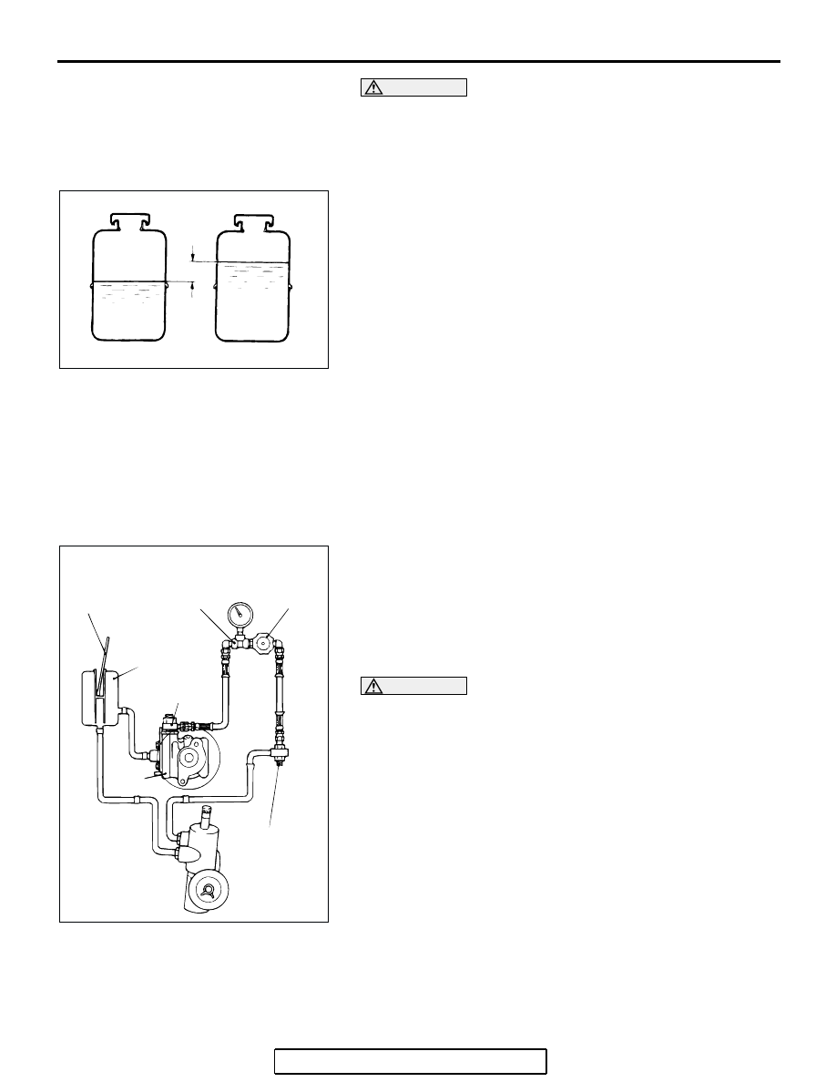
9. Confirm that the change in the fluid level is no more than 5 

mm (0.2 inch) when the engine is stopped.

10.If the change of the fluid level is 5 mm (0.2 inch) or more, 

the air has not been completely bled from the system. The 
air bleeding procedure must be repeated.

OIL PUMP PRESSURE TEST

M1372002300337

Required Special Tools:

• MB990662: Power Steering Oil Pressure Gauge

• MB991548: Power Steering Oil Pressure Gauge Adapter 

(Pump Side)

• MB991549: Power Steering Oil Pressure Gauge Adapter 

(Hose Side)

1. Disconnect the pressure hose from the oil pump, and then 

connect special tools MB991548, MB990662 and 
MB991549.

2. Bleed air, then turn the steering wheel several times while 

the vehicle is not moving so that the temperature of the fluid 
rises to approximately 50 

− 60°C (122 − 140°F).

3. Start the engine and idle it.

CAUTION

The pressure gauge shut-off valve must not remain closed 
for more than 10 seconds.
4. Fully close the shut-off valve of the pressure gauge and 

measure the oil pump relief pressure to confirm that it is 
within the standard value range. Open it again immediately 
after checking the pressure.

Standard value:

2.4L engine: 8.3 

 8.8 MPa (1,204  1,276 psi)

3.8L engine: 9.3 

 9.8 MPa (1,349  1,421 psi)

5. If it is not within the standard value, replace the oil pump.
6. Check whether or not the hydraulic pressure is the standard 

value when no-load conditions are created by fully opening 
the shut-off valve of the pressure gauge.

Standard value: 0.8 

 1.0 MPa (116  145 psi)

7. If it is not within the standard value, the probable cause is a 

malfunction of the oil line or steering gear, so check these 
parts and repair as necessary.

ACX01131

WHILE ENGINE
RUNNING

AC

FLUID LEVEL CHANGE:WITHIN 5 mm (0.2 in)

WHILE ENGINE
STOPPED

ACX01133

THERMO-
METER

RESERVOIR

ADAPTER
(MB991548)

OIL
PUMP

ADAPTER
(MB991549)

AB

SHUT-OFF VALVE
(FULLY CLOSED)

PRESSURE
GAUGE
(MB990662)

ON-VEHICLE SERVICE

TSB Revision

POWER STEERING

37-23

8. Turn the steering wheel all the way to the left or right; then 

check the retention hydraulic pressure.

Standard value:

2.4L engine: 8.3 

 8.8 MPa (1,204  1,276 psi)

3.8L engine: 9.3 

 9.8 MPa (1,349  1,421 psi)

9. If not the standard value, overhaul or replace the steering 

gear. Remeasure fluid pressure.

10. Remove special tools MB991548, MB990662 and 

MB991549, connect the pressure hose to the oil pump, and 
then tighten the eye bolt to the specified torque.

Tightening torque: 57 

± 7 Nm (42 ± 5 ft-lb)

11. Bleed the system (Refer to 

P.37-21

).

POWER STEERING PRESSURE SWITCH CHECK

M1372007200346

Required Special Tools:

• MB990662: Power Steering Oil Pressure Gauge

• MB991548: Power Steering Oil Pressure Gauge Adapter 

(Pump Side)

• MB991549: Power Steering Oil Pressure Gauge Adapter 

(Hose Side)

1. Disconnect the pressure hose from the oil pump, and then 

connect the special tools MB991548, MB990662 and 
MB991549.

2. Bleed air, and then turn the steering wheel several times 

while the vehicle is not moving so that the temperature of 
the fluid rises to approximately 50 

− 60°C (122 − 140°F).

3. The engine should be idling.
4. Disconnect the connector for the oil pressure switch, and 

place an ohmmeter at the switch.

5. Gradually close the shut-off valve of the pressure gauge and 

increase the hydraulic pressure, then check whether or not 
the hydraulic pressure that activates the switch is the 
standard value.

Standard value: 1.8 

 2.4 MPa (261  348 psi)

6. Gradually open the shut-off valve and reduce the hydraulic 

pressure; then check whether or not the hydraulic pressure 
that deactivates the switch is the standard value.

Standard value: 0.8 

 2.4 MPa (116  348 psi)

7.  Remove special tools MB991548, MB990662 and 

MB991549, connect the pressure hose to the oil pump, and 
then tighten the eye bolt to the specified torque.

Tightening torque: 57 

± 7 Nm (42 ± 5 ft-lb)

8. Bleed the system. (Refer to 

P.37-21

).

ACX01134 AB

THERMO-
METER

ADAPTER
(MB991548)

RESERVOIR

OIL
PUMP

ADAPTER
(MB991549)

SHUT-OFF
VALVE

PRESSURE
GAUGE
(MB990662)

ON-VEHICLE SERVICE

TSB Revision

POWER STEERING

37-24

TIE ROD END BALL JOINT DUST COVER CHECK

M1372008600284

1. Press the dust cover with your finger to check whether the 

dust cover is cracked or damaged.

2. If the dust cover is cracked or damaged, replace the tie rod 

end.
NOTE: If the dust cover is cracked or damaged, the ball joint 
could be damaged.

STEERING COLUMN SHAFT ASSEMBLY SHOCK 
ABSORBING MECHANISM CHECK

M1372013500131

• If a collision occurs or severe impact is applied to the steer-

ing wheel, the collision energy absorbing mechanism (slide 
plate, ripping plate, tilt pin) may have operated. Once the 
mechanism has operated, it will be inoperative even if there 
is no apparent damage. Determine if the steering column 
shaft can be reused by the following procedure. If the colli-
sion energy absorbing mechanism has already operated, 
replace the steering column assembly.

• If any excessive radial or axial free play on the steering 

wheel is found with the tilt lever in the lock position, always 
check the steering column assembly.

WARNING

1.

If the vehicle continues to be driven after the colli-
sion absorbing mechanism has operated, the 
steering column shaft may be damaged while driv-
ing.

2.

If there is a slack in the one-way capsule, do not 
attempt to repair it. Replace the steering column 
assembly.

Inspection Procedure

1. Remove the steering column covers (lower and upper).

CAUTION

Do not release the tilt lever until the steering column has 
been installed to complete this inspection procedure.
2. Place the tilt lever in the locked position.
3. Loosen the two upper steering column mounting bolts by 

two turns.

4. Hold the steering wheel, and then try to rock it. If there is a 

radial or axial free play, replace the steering column 
assembly.

AC308268 AC

SLIDE PLATE

RIPPING PLATE

TILT PIN

ON-VEHICLE SERVICE

TSB Revision

POWER STEERING

37-25

5. Check the tilt pin fixing detent of the lower bracket for 

deformation. If there is a deformation, replace the steering 
column assembly.

CAUTION

• Be careful that nothing is pinched between the one-way 

capsules and the body.

• Do not release the tilt lever until the steering column 

has been installed to complete this inspection proce-
dure.

6. If no problem is found during the inspection, tighten the 

steering column assembly mounting bolts to the specified 
torque.

Tightening torque: 12 

± 2 Nm (102 ± 22 in-lb)

AC308269 AB

TILT PIN

DETENT


Content   ..  1516  1517  1518  1519   ..