Mitsubishi Galant 9G. Manual - part 1517


  Index      Mitsubishi     Mitsubishi Galant 9G - service repair manual


Search            


Content   ..  1515  1516  1517  1518   ..


Mitsubishi Galant 9G. Manual - part 1517


ON-VEHICLE SERVICE

TSB Revision

POWER STEERING

37-18

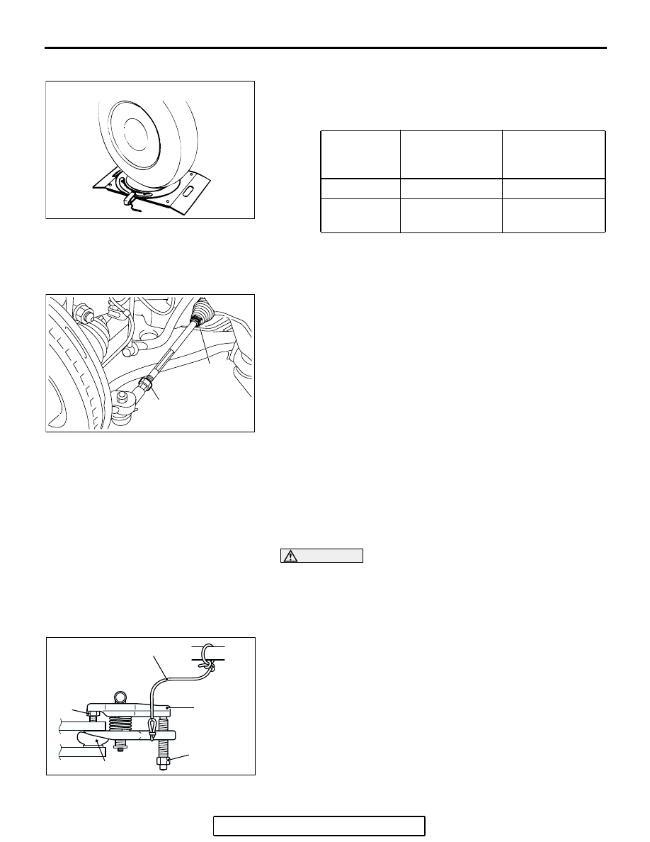
STEERING ANGLE CHECK

M1372001100396

1. Place the front wheel on a turning radius gauge and 

measure the steering angle.

Standard value:

2. If the steering angle is not within the standard value, adjust 

the toe as follows. 

Standard value: 0 

± 3 mm (0 ± 0.12 inch)

(1) Loosen the jam nut, and unclip the bellows.
(2) Adjust the toe by turning the left and right tie rod 

turnbuckles by the same amount (in opposite directions).
NOTE: The toe will move out as the left turnbuckle is 
turned toward the front of the vehicle and the right turn-
buckle is turned toward the rear of the vehicle.

(3) Tighten the jam nut to the specified torque, and tighten 

the bellows by the clip.

Tightening torque: 52 

± 2 Nm (38 ± 2 ft-lb)

3. Recheck the steering angle.

TIE ROD END BALL JOINT BREAKAWAY 
TORQUE CHECK

M1372001500305

Required Special Tools:

• MB990326: Preload Socket

• MB991897: Ball Joint Remover

CAUTION

• Do not remove the nut from ball joint. Loosen it and use 

special tool MB991897 to avoid possible damage to the 
ball joint threads.

• Hang special tool MB991897 with a cord to prevent it 

from falling. 

1. Install special tool MB991897 as shown in the figure.

ITEM

VEHICLES WITH 
16-INCH 
WHEELS

VEHICLES WITH 
17-INCH 
WHEELS

Inner wheel

37

°12' ± 2°00'

33

°48' ± 2°00'

Outer wheel
(reference)

30

°18'

28

°18'

AC000756AB

AC305785

AB

JAM NUT

CLIP

AC208247AC

CORD

BOLT

MB991897

NUT

BALL JOINT

ON-VEHICLE SERVICE

TSB Revision

POWER STEERING

37-19

2. Turn the bolt and knob as necessary to make the jaws of 

special tool MB991897 parallel, tighten the bolt by hand and 
confirm that the jaws are still parallel.
NOTE: When adjusting the jaws in parallel, make sure the 
knob is in the position shown in the figure.

3. Tighten the bolt with a wrench to disconnect the tie rod end.

4. Move the ball joint stud several times and install the nut on 

the stud. Using special tool MB990326, measure the ball 
joint breakaway torque.

Standard value: 0.5 

 3.5 Nm (4.4  31.0 in-lb)

5. If the breakaway torque exceeds the standard value, replace 

the tie rod end assembly.

6. If the breakaway torque is under the standard value, check 

the ball joint for end play or ratcheting. If there is no end play 
or ratcheting, the ball joint can be re-used.

CAUTION

Always use a new ball joint nut, as it is a self-locking nut.
7. Install the tie rod end to the knuckle, then tighten a new 

self-locking nut to the specified torque.

Tightening torque: 29 

± 4 Nm (21 ± 3 ft-lb)

STATIONARY STEERING EFFORT CHECK

M1372001700354

1. With the vehicle stopped on a flat and paved surface, turn 

the steering wheel to the straight ahead position.

2. Start the engine and allow to idle.
3. Attach a spring scale to the outer circumference of the 

steering wheel and measure the steering force required to 
turn the steering wheel from the straight ahead position to 
the left and right (within a range of 1.5 turns). Also check to 
be sure that there is no significant change in the required 
steering effort.

Standard value:
Steering effort: 30 N (6.7 lb) or less
Fluctuation allowance: 5.9 N (1.33 lb) or less

4. If the measured value exceeds the standard value, refer to 

Inspection Procedure 2 "Difficult Steering Wheel Operation 
(Insufficient Power Assist)" 

P.37-5

.

AC106821

KNOB

PARALLEL

BOLT

GOOD

BAD

AB

ACX01129 AB

MB990326

ACX01122 AB

ON-VEHICLE SERVICE

TSB Revision

POWER STEERING

37-20

STEERING WHEEL RETURN TO CENTER CHECK

M1372001800339

Conduct a road test:
1. Make both gradual and sudden turns and check the steering 

wheel return. 

2. At a vehicle speed of approximately 35 km/h (22 mph), turn 

the steering wheel 90 degrees, hold a few seconds, then 
release. If the steering wheel then returns 70 degrees or 
more, the return can be judged as satisfactory.
NOTE: There will be a momentary feeling or "heaviness" 
when the wheel is turned quickly, but this is not abnormal. 
(Oil pump discharge amount is especially apt to be insuffi-
cient during idling.) 

DRIVE BELT TENSION CHECK

M1372001900284

Refer to GROUP 00, Maintenance Service 

− Drive Belts 

P.00-45

.

FLUID LEVEL CHECK

M1372002000303

1. Park the vehicle on a flat, level surface.
2. Start the engine, and then turn the steering wheel several 

times to raise the temperature of the fluid to approximately 
50 

− 60°C (122 − 140°F).

3. With the engine running, turn the wheel all the way to the left 

and right several times.

4. Check the fluid in the oil reservoir for foaming or milkiness. 

Check the difference of the fluid level when the engine is 
stopped, and while it is running. If the fluid contains air or 
has milky appearance, or the fluid level fluctuate by 5 mm 
(0.2 inch) or more, power steering system air bleeding 
should be done.

ACX01130AB

70˚

70˚

ACX01131

WHILE ENGINE
RUNNING

AC

FLUID LEVEL CHANGE:WITHIN 5 mm (0.2 in)

WHILE ENGINE
STOPPED

ON-VEHICLE SERVICE

TSB Revision

POWER STEERING

37-21

FLUID REPLACEMENT

M1372002100366

1. Raise and support the front wheels.
2. Disconnect the return hose connection, and then connect a 

vinyl hose to the return hose, and drain the fluid into a 
container.

3. Disconnect the ignition coil connectors (refer to GROUP 16, 

Ignition Coil 

P.16-40

 <2.4L ENGINE>, 

P.16-41

 <3.8L 

ENGINE>).

4. While operating the starter motor intermittently, turn the 

steering wheel all the way to the left and right several times 
to drain all of the fluid.

5. Connect the return hose securely, and then secure with the 

clip.

6. Fill the oil reservoir with GENUINE MITSUBISHI POWER 

STEERING FLUID up to the lower mark of the reservoir, and 
then bleed the air.

POWER STEERING SYSTEM AIR BLEEDING

M1372002200352

Perform air bleeding procedure as necessary after replacing 
the steering gear, oil pump or the steering fluid lines.
1. Raise and support the front wheels.
2. Disconnect the ignition coil connectors (Refer to GROUP 16, 

Ignition Coil 

P.16-40

 <2.4L ENGINE>, 

P.16-41

 <3.8L 

ENGINE>).

CAUTION

Perform air bleeding only while cranking the engine. Do 
not perform air bleeding while the engine is running. If you 
do so, air in the fluid will be increased and air bleeding will 
become more difficult. During air bleeding, refill the steer-
ing fluid so that the level never falls below the lower mark 
on the dipstick.
3. Turn the steering wheel all the way to the left and right five 

or six times while using the starter motor to crank the engine 
intermittently several times (for 15 to 20 seconds).

4. Connect the ignition coil connectors (Refer to GROUP 16, 

Ignition Coil 

P.16-40

 <2.4L ENGINE>, 

P.16-41

 <3.8L 

ENGINE>).

5. Start the engine and allow to idle.
6. Turn the steering wheel to the left and right until there are no 

air bubbles in the oil reservoir.

7. Confirm that the fluid is not milky, and that the level is 

between the high and low dipstick marks.

8. Confirm that there is very little change in the fluid level when 

the steering wheel is turned left and right.

AC206743

RETURN
HOSE

VINYL HOSE

AB


Content   ..  1515  1516  1517  1518   ..