Content .. 1517 1518 1519 1520 ..
Mitsubishi Galant 9G. Manual - part 1519
STEERING WHEEL
TSB Revision
POWER STEERING
37-26
STEERING WHEEL
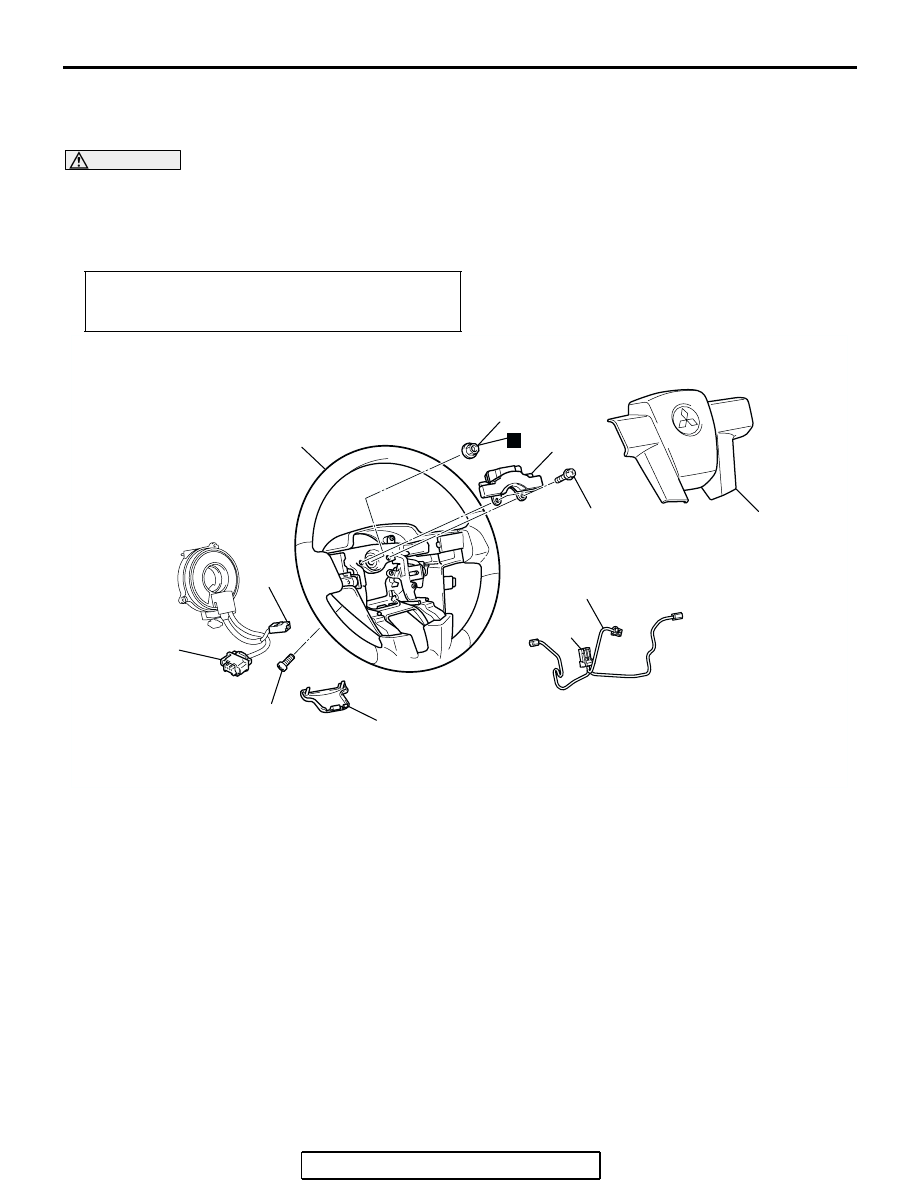
REMOVAL AND INSTALLATION
M1372011400224
WARNING
•
Before removing the steering wheel and air bag module assembly, refer to GROUP 52B,
Service Precautions (
) and Air Bag Module and Clock Spring (
•
When removing and installing the steering wheel, do not let it bump against the air bag
module.
NOTE: For air bag module removal, refer to GROUP
52B, Air Bag Module and Clock Spring
Required Special Tool:
• MB990803: Steering Wheel Puller
Post-installation Operation
• Checking Steering Wheel Position with Wheels Straight
Ahead
AC306560
41 ± 8 N·m
30 ± 6 ft-lb
1
3
4
6
9.0 ± 2.0 N·m
80 ± 17 in-lb
AB
N
3.9 ± 0.9 N·m
35 ± 8 in-lb
2
5
2
2
REMOVAL STEPS
1. STEERING WHEEL LOWER
COVER
<<A>>
2. CONNECTORS (FOR HORN, AIR
BAG MODULE, AND STEERING
WHEEL REMOTE CONTROL
HARNESS)
3. AIR BAG MODULE
4. STEERING WHEEL DYNAMIC
DAMPER
5. STEERING WHEEL REMOTE
CONTROL HARNESS
<<B>>
6. STEERING WHEEL ASSEMBLY
INSTALLATION STEPS
•
CLOCK SPRING MATING MARK
ALIGNMENT (REFER TO GROUP
52B, AIR BAG MODULE AND
CLOCK SPRING
6. STEERING WHEEL ASSEMBLY
5. STEERING WHEEL REMOTE
CONTROL HARNESS
4. STEERING WHEEL DYNAMIC
DAMPER
3. AIR BAG MODULE
2. CONNECTORS (FOR HORN, AIR
BAG MODULE, AND STEERING
WHEEL REMOTE CONTROL
HARNESS)
1. STEERING WHEEL LOWER
COVER
INSTALLATION STEPS