Mitsubishi Pajero Pinin. Manual - part 330


  Index      Mitsubishi     Mitsubishi Pajero Pinin - service repair manual 2001 year


Search            


Content   ..  328  329  330  331   ..


Mitsubishi Pajero Pinin. Manual - part 330


CHASSIS ELECTRICAL – 

Headlamp, Front Turn-signal Lamp and Front Fog Lamp

54A-36

REMOVAL SERVICE POINT

A

A

"

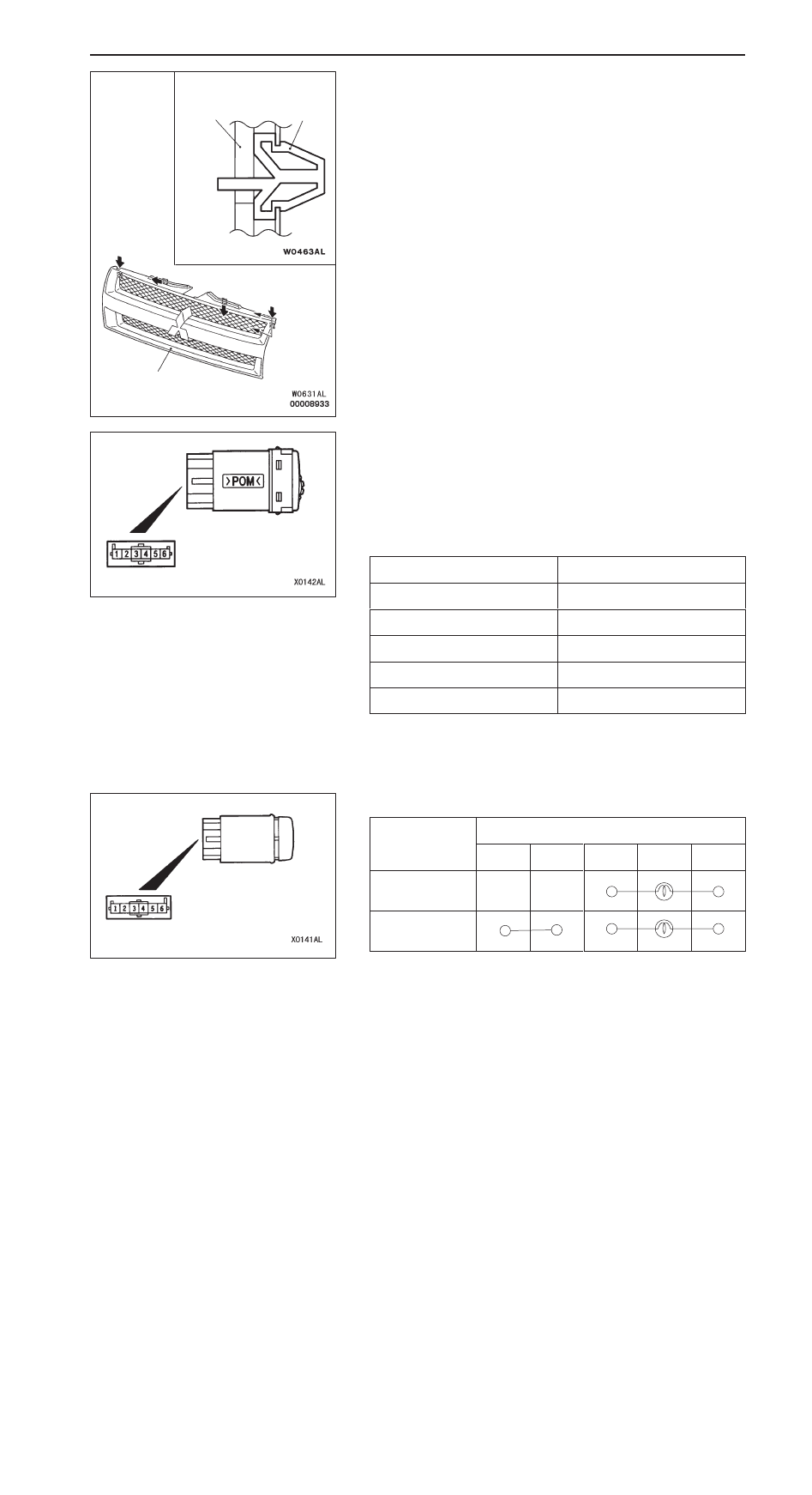
RADIATOR GRILLE REMOVAL

1.

Pull the radiator grille toward you gently, and press the
clip tab with a flat-tipped screwdriver toward the arrow
to remove the radiator grille.

2.

Remove the clips from the body, and install them to the
radiator grille temporarily for reinstallation.

INSPECTION

HEADLAMP LEVELING SWITCH CONTINUITY CHECK

1.

Check the continuity between terminals 4 and 5
(illumination circuit).

2.

Operating the headlamp leveling switch, check that the
resistance between terminals 4 and 5 meets the condition
below.

Switch position

Resistance value

0

12 k

1

5.1 k

2

2.7 k

3

1.5 k

4

620 

FOG LAMP SWITCH CONTINUITY CHECK

Switch position

Terminal No.

1

2

3

ILL

4

Released

Pressed

Radiator grille

Radiator grille

Clip

Section A – A

A

A

CHASSIS ELECTRICAL – 

Headlamp, Front Turn-signal Lamp and
Front Fog Lamp/Side Turn-signal Lamp

54A-37

FRONT FOG LAMP RELAY CONTINUITY CHECK

Battery voltage

Terminal No.

1

3

4

5

Not supplied

Supplied

SIDE TURN-SIGNAL LAMP

SPECIAL TOOL

Tool

Number

Name

Use

MB990784

Ornament remover

Removal of side turn-signal lamp

TROUBLESHOOTING

The side turn-signal lamp is controlled by the smart wiring system (SWS).
For troubleshooting, refer to GROUP 54B – Troubleshooting.

Front fog lamp relay

CHASSIS ELECTRICAL – 

Side Turn-signal Lamp/Room Lamp/Rear
Combination Lamp, Rear Fog Lamp

54A-38

SIDE TURN-SIGNAL LAMP

REMOVAL SERVICE POINT

SIDE TURN-SIGNAL LAMP REMOVAL

Use a special tool to remove the lock from the fender panel,
and then remove the side turn-signal lamp.

ROOM LAMP

TROUBLESHOOTING

The room lamp is controlled the smart wiring system (SWS).
For troubleshooting, refer to GROUP 54B – Troubleshooting.

REAR COMBINATION LAMP, REAR FOG LAMP

SPECIAL TOOLS

Tool

Number

Name

Use

MB990784

Ornament remover

Removal of side turn-signal lamp

TROUBLESHOOTING

The tail lamp, turn-signal lamp and rear fog lamp are controlled by the smart wiring system (SWS). For
troubleshooting, refer to GROUP 54B – Troubleshooting.

MB990784

Front of vehicle

CHASSIS ELECTRICAL – 

Rear Combination Lamp, Rear Fog Lamp

54A-39

REAR COMBINATION LAMP, REAR FOG LAMP

REMOVAL AND INSTALLATION <L.H. drive vehicles>

Section A – A

Claw

Instrument
panel

1

2

6

5

8

7

3

5

4

A

A

A

A

2.5 

±

 0.2 Nm

Section B – B

Body
panel

Gronmet

3

1

BX0283AL

Fog lamp switch removal steps

1. Switch panel
2. Fog lamp switch

Rear combination lamp removal
steps

D

Quarter Trim Removal and Installation
(Refer to GROUP 52A)

3. Rear combination lamp
4. Socket assembly
5. Bulb

Rear fog lamp removal steps

D

Rear mad guard 
(Refer to GROUP 51)

D

Rear splash shield

6. Rear fog lamp
7. Bracket
8. Socket


Content   ..  328  329  330  331   ..