Mitsubishi Pajero Pinin. Manual - part 263


  Index      Mitsubishi     Mitsubishi Pajero Pinin - service repair manual 2001 year


Search            


Content   ..  261  262  263  264   ..


Mitsubishi Pajero Pinin. Manual - part 263


STEERING – 

Steering Wheel and Shaft

37A-13

REMOVAL SERVICE POINTS

A

A

"

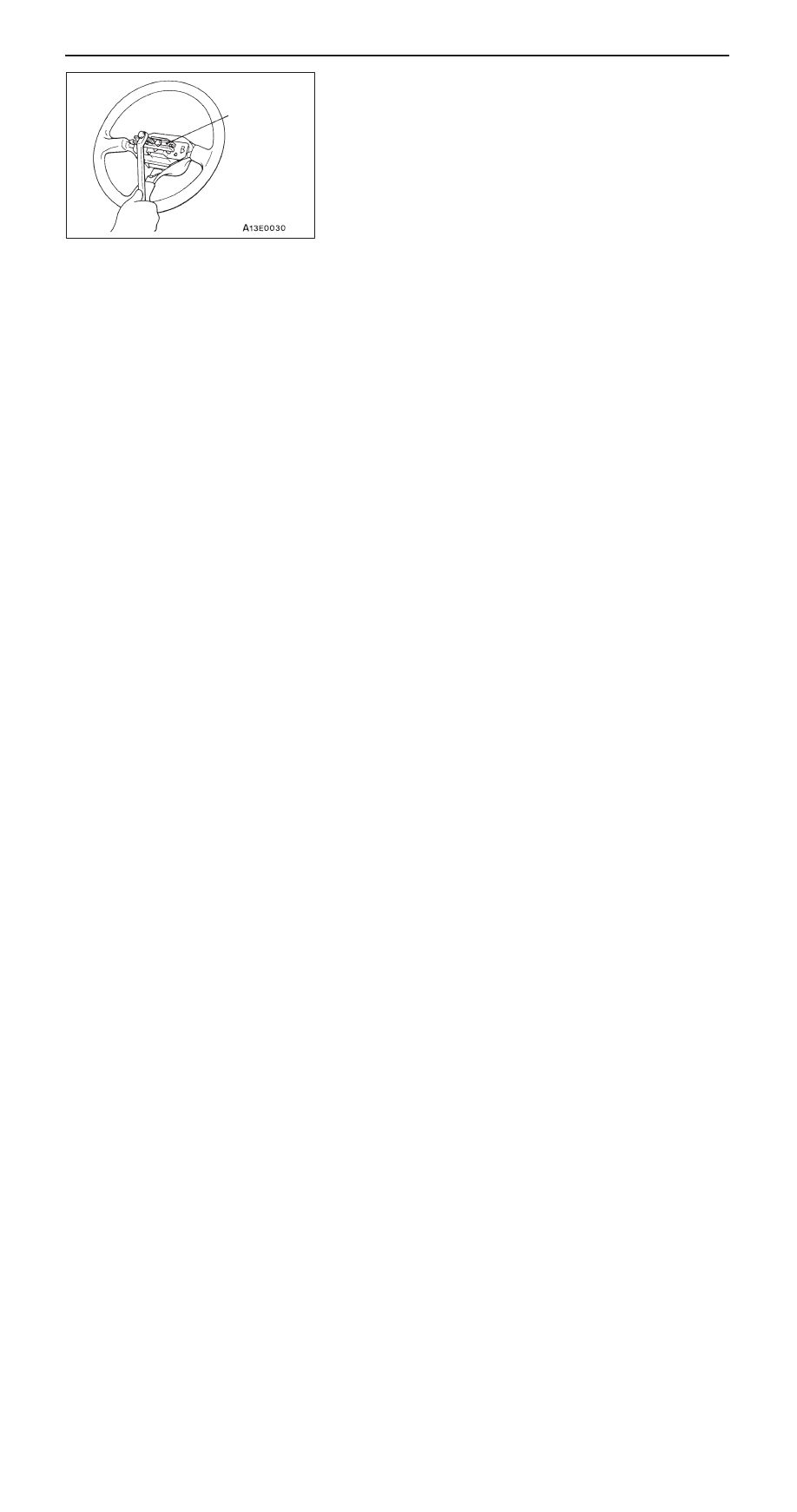
STEERING WHEEL REMOVAL

MB990803

STEERING – 

Steering Wheel and Shaft

37A-14

DISASSEMBLY AND REASSEMBLY

BW0581AL

1

4

3

2

AW1122AL

<L.H. drive vehicles>

<R.H. drive vehicles>

5

17 Nm

1

2

3

5

Disassembly steps

A

A

" "

A

A

1. Special bolt

"

A

A

2. Steering lock bracket

"

A

A

3. Steering lock cylinder assembly

4. Shaft assembly

<L.H. drive vehicles>

5. Steering column shaft assembly

DISASSEMBLY SERVICE POINT

A

A

"

SPECIAL BOLT REMOVAL

1.

In the special bolt, drill a hole deep enough for the tap
to stand.

2.

Using a left-hand tap, remove the special bolt.

REASSEMBLY SERVICE POINT

"

A

A

STEERING LOCK CYLINDER ASSEMBLY/
STEERING LOCK BRACKET/SPECIAL BOLT
INSTALLATION

1.

When installing the steering lock cylinder assembly and
steering lock bracket to the steering column assembly,
temporarily install the steering lock in alignment with the
column boss.

2.

Check that the steering lock works properly. Then, tighten
the special bolts until the heads twists off.

Steering
lock bracket

Steering lock body

Special bolt

Left-hand tap

STEERING – 

Power Steering Gear Box and Linkage

37A-15

POWER STEERING GEAR BOX AND LINKAGE

REMOVAL AND INSTALLATION

Caution: SRS
On vehicles with SRS, before removing steering gear box, refer to GROUP 52B. Also, put the front
wheels in straight–ahead position and remove the ignition key. Failure to do so may damage the
SRS clock spring and render the SRS air bag inoperative, which results serious driver injury.

Pre-removal Operation

D

Power Steering Fluid Draining (Refer to P.37A-9.)

D

Under Cover Removal

Post-installation Operation

D

Check the Dust Cover for Cracks or Damage by
Pushing it with Finger.

D

Under Cover Installation

D

Power Steering Fluid Supplying and bleeding
(Refer to P.37A-9.)

D

Checking Steering Wheel Position with Wheels
Straight Ahead

D

Front Wheel Alignment Check and Adjustment 
(Refer to GROUP 33A – On-vehicle Service.)

2

13

18 Nm

12 Nm

70 Nm

2

3

5

1

34 Nm

15 – 33 Nm

11

8

10

15 Nm

4

6

<L.H. drive vehicles>

12

9

STEERING – 

Power Steering Gear Box and Linkage

37A-16

15 – 33 Nm

2

13

18 Nm

12 Nm

70 Nm

7

5

2

3

5

1

34 Nm

12 Nm

8

11

9

10

15 Nm

4

6

<R.H. drive vehicles>

12

Removal steps

1. Steering gear and joint connecting bolt
2. Splash shield
3. Split pin

A

A

"

4. Tie rod end and knuckle

connection

"

B

A

5. Return hose

"

A

A

6. Pressure hose

7. Nut <R.H drive vehicles>
8. Pressure tube
9. Return tube

10. O-ring

11. Cylinder clamp

12. Gear housing clamp

A

B

"

13. Steering and gear linkage


Content   ..  261  262  263  264   ..