Mitsubishi Pajero Pinin. Manual - part 262


  Index      Mitsubishi     Mitsubishi Pajero Pinin - service repair manual 2001 year


Search            


Content   ..  260  261  262  263   ..


Mitsubishi Pajero Pinin. Manual - part 262


STEERING – 

On-vehicle Service

37A-9

POWER STEERING FLUID LEVEL CHECK

1.

Park the vehicle on a flat, level surface and start the engine.
Without the vehicle moving, turn the steering wheel several
times until the fluid reaches 50 to 60

_

C.

2.

With the engine running, turn the wheel fully left and right
several times.

3.

Check the fluid in the oil reservoir for foaming or milkiness.
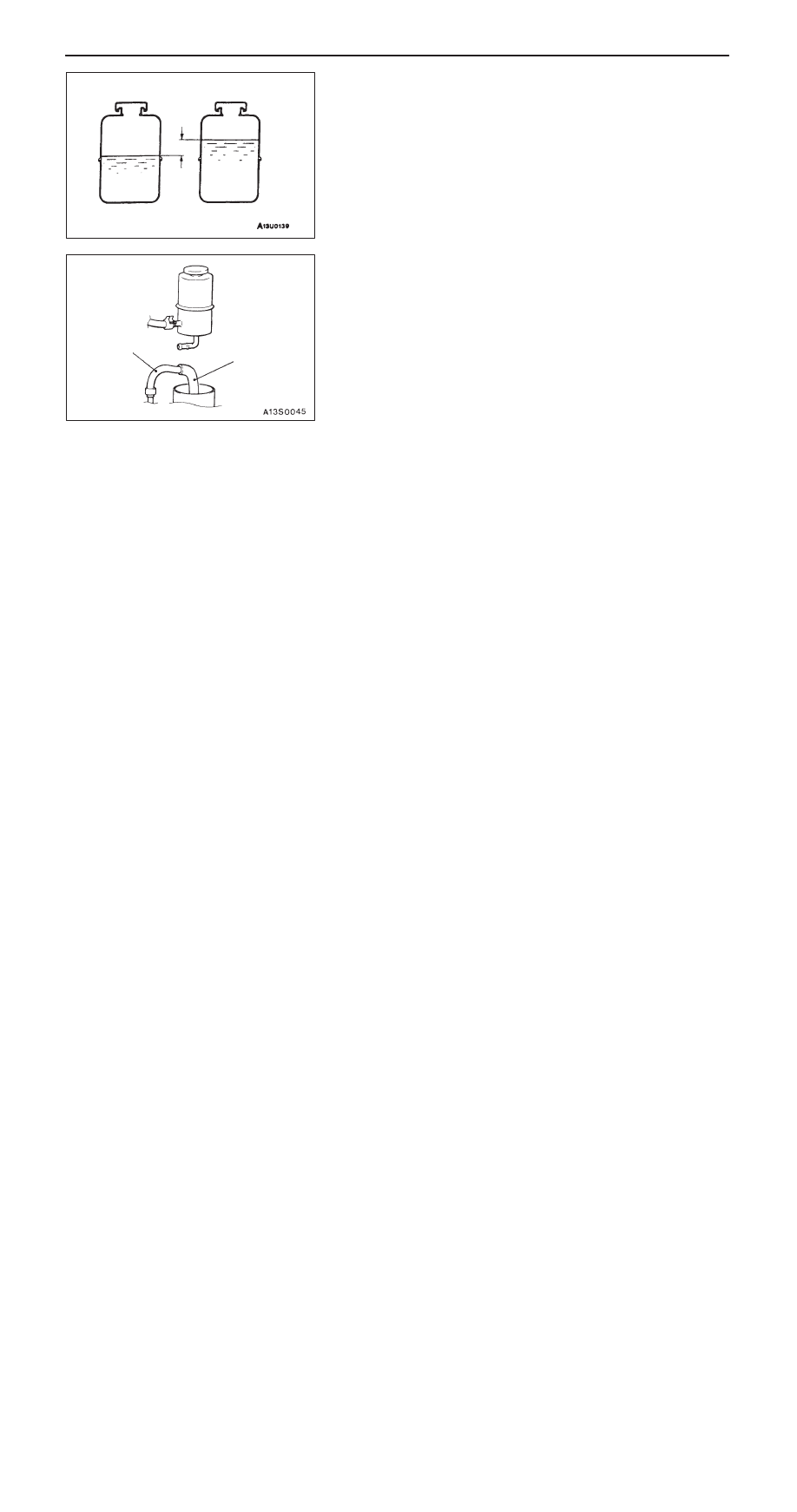
4.

Check difference in fluid level between the engine stopped
and running. If the difference is 5 mm or more, bleed
air.

POWER STEERING FLUID REPLACEMENT

1.

Jack up the vehicle and support the front wheels with
rigid racks.

2.

Disconnect the return hose.

3.

Connect a vinyl hose to the return hose and drain fluid
into a container.

4.

Disconnect the ignition coil connectors. (Refer to
GROUP16 – Ignition System.)

5.

Cranking the engine several times intermittently with the
starter, turn the steering wheel fully left and right to drain
the fluid.

6.

Connect the return hose and secure it with the clip.

7.

Fill the oil reservoir with specified fluid up to between
“MAX” and “MIN” marks, and then bleed air.

Specified fluid:

Automatic transmission fluid
DEXRON or DEXRON 

II

Caution
Do not use ATF-SP 

II 

as it damages the components

of the power steering.

POWER STEERING SYSTEM BLEEDING

1.

Jack up the vehicle and support the front wheels with
rigid racks.

2.

Disconnect the ignition coil connectors. Cranking the
engine with the starter several times intermittently (during
15 to 20 seconds), turn the steering wheel left and right
fully five or six times.

Caution
(1) During the bleeding, refill the fluid so that the level

is always above “MIN” mark on the oil reservoir.

(2) Be sure to bleed air only while cranking. If the

bleeding is done with the engine running, the air
will be broken up and absorbed into the fluid.

3.

Connect the ignition coil connectors and idle the engine.

4.

Turn the steering wheel left and right fully until no bubbles
comes out in the oil reservoir.

5.

See that the fluid is not milky and that the fluid level is
between “MAX” and “MIN” marks.

6.

See that the fluid level changes little when the steering
wheel is turned left and right.

7.

Check difference in fluid levels between the engine stopped
and running.

Fluid level change: Within 5 mm

While engine
running

While engine
stopped

Return hose

Vinyl hose

STEERING – 

On-vehicle Service

37A-10

8.

If the level changes more than 5 mm, the air is badly bled.
So, bleed air again.

Caution
(1) If the fluid level rises suddenly after the engine

is stopped, the bleeding is incomplete.

(2) Incomplete bleeding causes abnormal noises from

the pump and the flow-control valve. This could
lessen the life of the pump and the other parts.

OIL PUMP PRESSURE TEST

1.

Disconnect the pressure hose from the oil pump, and then
connect the special tools.

2.

Bleed air. Without the vehicle moving, turn the steering
wheel several times to raise the fluid temperature to 50
to 60

_

C.

3.

Start the engine and idle at 1,000

±

100 r/min.

4.

Fully close the shut-off valve of the pressure gauge and
measure the oil pump relief pressure.

Standard value: 8.3 – 9.0 MPa

5.

If the standard value is not met, disassemble and assemble
the oil pump again. Then, remeasure oil pressure.

6.

With the pressure gauge shut–off valve fully open, check
the hydraulic pressure in unladen condition.

Standard value: 0.2 – 0.7 MPa

7.

If the standard value is not met, the oil line or steering
gear is probably defective. So, repair and measure oil
pressure again.

8.

Turn the steering wheel fully either left or right and check
the retention hydraulic pressure.

Standard value: 8.3 – 9.0 MPa

9.

If the pressure is below the standard value, disassemble
and reassemble the steering gear. If above, disassemble
and reassemble the components of the oil pump flow
control valve. Then, measure oil pressure again.

10. Remove the special tools, and tighten the pressure hose

to the specified torque.

Tightening torque: 57 Nm

11. Bleed the system.

Fluid level change: Within 5 mm

While engine
running

While engine
stopped

Temperature
gauge

Pressure
gauge
(MB990662)

Shut-off valve

Adapter
(MB990993)

Oil
pump

Oil reservoir

Adapter
(MB990994)

STEERING – 

On-vehicle Service

37A-11

POWER STEERING OIL PRESSURE SWITCH
CHECK

1.

Disconnect the pressure hose from the oil pump and
connect the special tools.

2.

Bleed air. Without the vehicle moving, turn the steering
wheel several times to raise the fluid temperature to 50
to 60

_

C.

3.

Idle the engine.

4.

Disconnect the oil pressure switch connector and set an
ohmmeter in position.

5.

Gradually close the shut-off valve in the pressure gauge
to increase hydraulic pressure. Check that the hydraulic
pressure activating the switch meets the standard value.

Standard value: 1.5 – 2.0 MPa

6.

Gradually open the shut-off valve and reduce the hydraulic
pressure. Check that the hydraulic pressure deactivating
the switch meets the standard value.

Standard value: 0.7 – 2.0 MPa

7.

Remove the special tools and tighten the pressure hose
to the specified torque.

Tightening torque: 57 Nm

8.

Bleed the system.

BALL JOINT DUST COVER CHECK

1.

Check the dust cover for cracks or damage by pushing
it with finger.

2.

If the dust cover is cracked or damaged, replace the tie
rod end.

NOTE
A cracked or damaged dust cover may damage the ball
joint.

Temperature
gauge

Pressure
gauge
(MB990662)

Shut-off valve

Adapter
(MB990993)

Oil
pump

Reservoir

Adapter
(MB990994)

STEERING – 

Steering Wheel and Shaft

37A-12

STEERING WHEEL AND SHAFT

REMOVAL AND INSTALLATION

Caution:
1.

Before removing the air bag module and clock spring, refer to GROUP 52B – Service Precautions
and Air Bag Module and Clock Spring.

2.

Use an earth bolt for one of the steering shaft assembly mounting bolts. The earth bolt has
mark “E” on its head.

Pre-removal Operation
Instrument Under Cover Removal
(Refer to GROUP 52A.)

Post-installation Operation

D

Instrument Under Cover Installation
(Refer to GROUP 52A.)

D

Checking Steering Wheel Position with Wheels
Straight Ahead

Standard bolt

12 Nm

22 Nm

Earth bolt

18 Nm

12 Nm

41 Nm

7

9

1

6

4

2

3

8

5

9 Nm

1

Removal steps

1. Air bag module <Refer to GROUP

52B>

A

A

"

2. Steering wheel
3. Lower column cover
4. Upper column cover
5. Clock spring and column switch as-

sembly <Refer to GROUP 52B>

6. Cover <A/T>

7. Key interlock cable <A/T>
8. Steering column shaft assembly

NOTE
When the air bag module assembly must be
removed, refer to GROUP 52B – Air Bag Modules
and Clock Spring.


Content   ..  260  261  262  263   ..