Mitsubishi Pajero Pinin. Manual - part 62
GDI –
Throttle Body
13A-114
THROTTLE BODY
REMOVAL AND INSTALLATION
Pre-removal and Post-installation Operation
D
Engine Coolant Draining and Supplying (Refer to
GROUP 14 – On-vehicle Service.)
D
Resonance Tank Removal and Installation (Refer
to GROUP 15.)
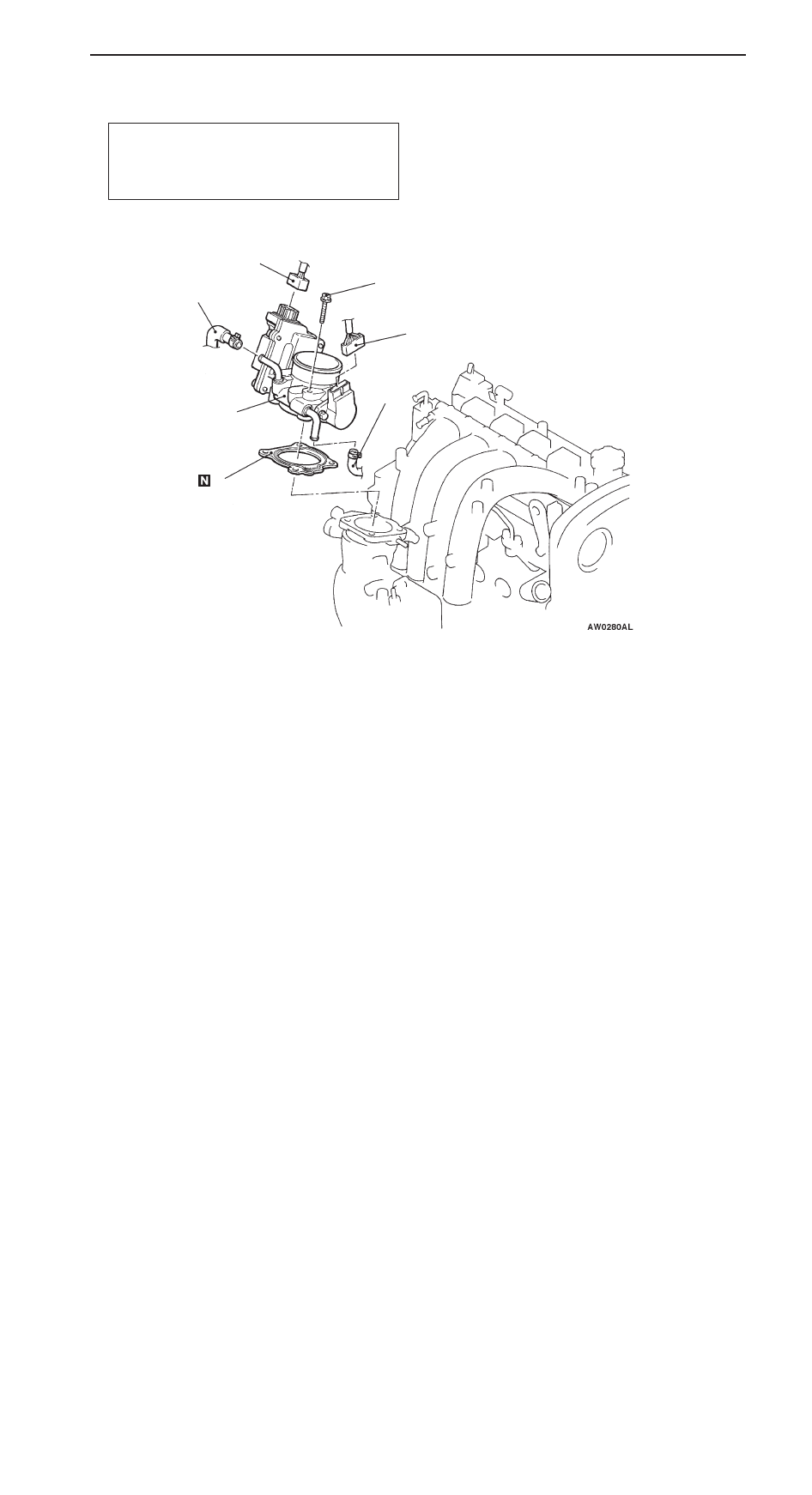
1
2
3
4
5
19 Nm
3
Removal steps
1. Throttle position sensor connector
connection
2. Throttle control servo connector con-
nection
3. Water hose connection
"
A
A
4. Throttle body assembly
5. Throttle body gasket
INSTALLATION SERVICE POINT
"
A
A
THROTTLE BODY INSTALLATION
If the throttle body is replaced, initialize the electronic-controlled
throttle valve system.
Initialization
Turn on the ignition switch, and turn it to LOCK (OFF) position
within one second. Then leave it for at least ten seconds
with the ignition switch in LOCK (OFF) position.