Mitsubishi Pajero Pinin. Manual - part 61


  Index      Mitsubishi     Mitsubishi Pajero Pinin - service repair manual 2001 year


Search            


Content   ..  59  60  61  62   ..


Mitsubishi Pajero Pinin. Manual - part 61


GDI – 

Fuel Pump (High Pressure) and Fuel Pressure Regulator (High Pressure)

13A-110

"

C

A

FUEL RETURN PIPE/FUEL PRESSURE
HOSE/FUEL FEED PIPE INSTALLATION

Apply a small amount of fresh engine oil to the O-ring.

Caution
Take care not to let any of the engine oil get inside the
fuel pump (high pressure), fuel pressure regulator (high
pressure) or the delivery pipe assembly.

"

D

A

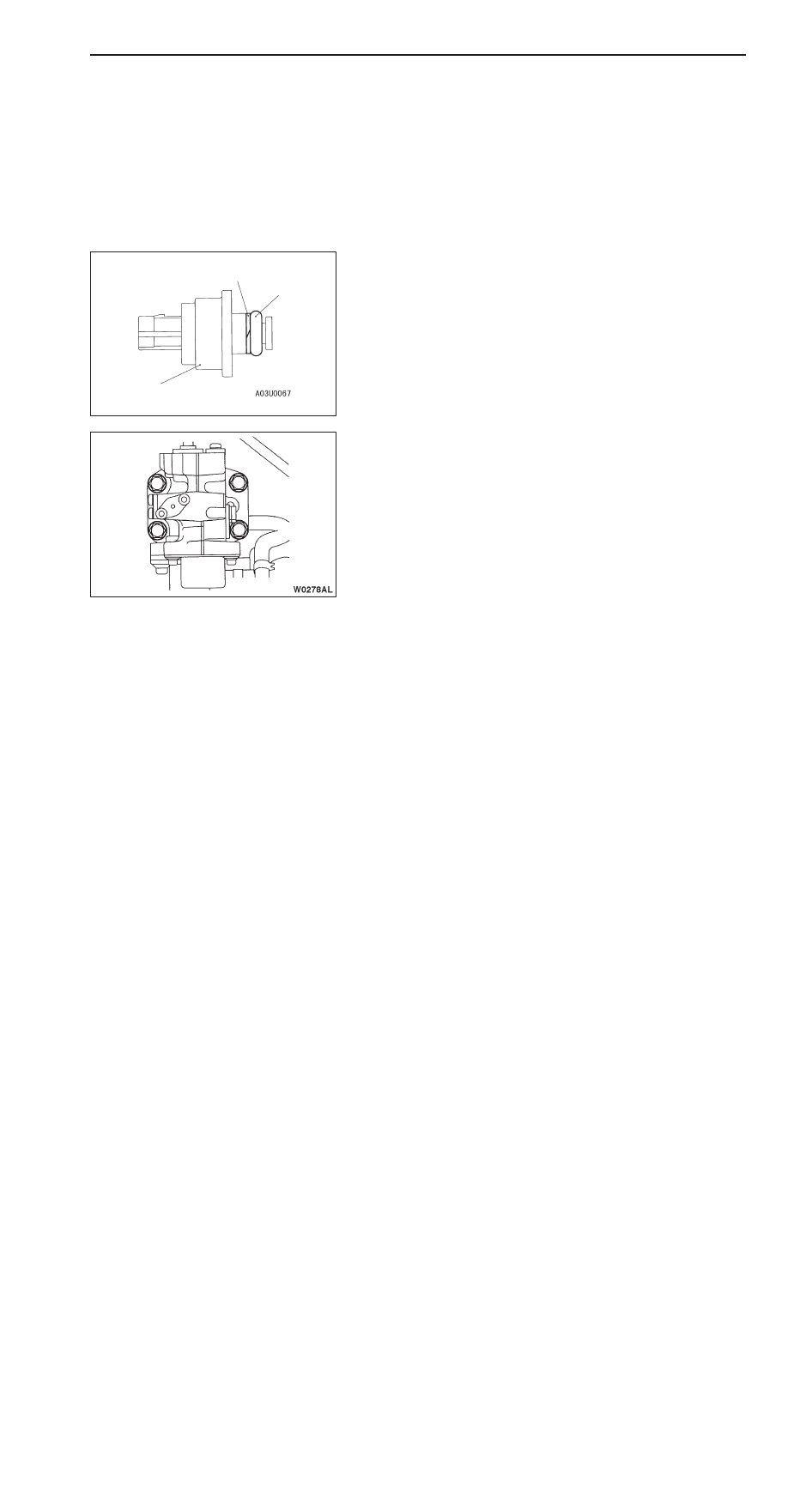
BACK-UP RING/O-RING INSTALLATION

Install the back-up ring and the O-ring as shown in the
illustration.

Caution
Take care not to install the back-up ring A for the injector,
fuel feed pipe or fuel return pipe by mistake. (Outer
diameter of the back-up ring for the fuel pressure sensor:
15.1 mm)

"

E

A

FUEL PUMP (HIGH PRESSURE) INSTALLATION

1.

Apply a small amount of fresh engine oil to the fuel pump
(high pressure) roller and O-ring.

2.

Install temporarily the fuel pump (high pressure) to the
cylinder head.

3.

Install the fuel feed pipe, and then tighten the fuel pump
(high pressure) mounting bolts to 5 Nm in the order shown
in the illustration.

4.

Tighten the bolts to 17 Nm in the order shown in the
illustration. The overall difference in tightening torque
between the four bolts should be within 2 Nm.

"

F

A

FUEL PUMP (HIGH PRESSURE) AIR BLEEDING

1.

Run the engine at 2,000 r/min for 15 seconds or more
in order to bleed the air.

NOTE
When removing the fuel pump (high pressure), air may
get into the fuel pump (high pressure). If air gets into
the fuel pump (high pressure), diagnosis code No.56 for
abnormal fuel pressure will be output.

2.

Use the MUT-

II

 to check the diagnosis code. If the

diagnosis code No.56 for fuel pressure sensor system
defect is output, erase it.

Back-up ring

O-ring

Fuel pressure sensor

1

2

3

4

GDI – 

Injector

13A-111

INJECTOR

REMOVAL AND INSTALLATION

Pre-removal and Post-installation Operation
Fuel Pressure Regulator (High Pressure) Removal and
Installation (Refer to P.13A-107.)

O-ring

Engine oil

1

2

3

4

5

6

11

20 – 25
Nm

10 – 13
Nm

7

8

9

10

12

10 – 13
Nm

13

14

15

16

14

1

2

3

4

O-ring

Removal steps

"

D

A

1. Fuel feed pipe

"

C

A

2. Back-up ring A

"

C

A

3. O-ring

"

C

A

4. Back-up ring B

A

A

"

5. Injector harness connector
6. Washer
7. Injector holder

A

B

" "

B

A

8. Delivery pipe assembly

9. Insulator

A

B

" "

B

A

10. Fuel injector assembly

11. Back-up ring

12. O-ring
13. Back-up ring
14. Fuel injector
15. Gasket

"

A

A

16. Corrugated washer

GDI – 

Injector

GDI – 

Injector

13A-112

REMOVAL SERVICE POINTS

A

A

"

INJECTOR HARNESS CONNECTOR
DISCONNECTION

Caution
Disconnect the battery (–) cable from its terminal before
carrying out this operation.

A

B

"

DELIVERY PIPE ASSEMBLY/FUEL INJECTOR
ASSEMBLY REMOVAL

Remove the delivery pipe assembly with the fuel injector
assembly still attached.

Caution
Be careful not to drop the fuel injector assembly when
removing the delivery pipe assembly.

INSTALLATION SERVICE POINTS

"

A

A

CORRUGATED WASHER INSTALLATION

Caution
The corrugated washer should always be replaced with
a new part.

"

B

A

FUEL INJECTOR ASSEMBLY/DELIVERY PIPE
ASSEMBLY INSTALLATION

1.

Apply a small amount of fresh engine oil to the O-ring.

Caution
Take care not to let any of the engine oil get inside
the delivery pipe assembly.

2.

While being careful not to damage the O-ring, turn the
fuel injector assembly to the left and right and connect
it to the delivery pipe assembly. After connecting, check
that the fuel injector turns smoothly.

3.

If the fuel injector does not turn smoothly, the cause may be
that the O-ring is getting caught. Remove the fuel injector,
check the O-ring for damage and re-connect the fuel
injector to the delivery pipe assembly and then re-check.

Corrugated washer

GDI – 

Injector

13A-113

4.

Align the mating marks on the delivery pipe assembly
and the fuel injector, and then install the delivery pipe
assembly with the injector assembly still attached.

5.

Install the delivery pipe and fuel injectors to the cylinder
head, and then tighten them provisionally.

6.

Install the injector holders and washers, and then tighten
them to the specified torque.

Caution
Observe the tightening torque.

7.

Tighten the delivery pipe and fuel injectors to the specified
torque in the order shown in the illustration.

"

C

A

BACK-UP RING B/O-RING/BACK-UP RING A
INSTALLATION

Install the back-up rings and the O-ring as shown in the
illustration.

Caution
Install the back-up ring B facing its cutaway surface toward
the opposite side of the O-ring as shown in the illustration.

"

D

A

FUEL FEED PIPE INSTALLATION

Apply a small amount of fresh engine oil to the O-ring.

Caution
Take care not to let any of the engine oil get inside the
fuel pump (high pressure), fuel pressure regulator (high
pressure) and delivery pipe.

Mat-
ing
marks

Fuel injector

Delivery pipe
assembly

3

1

2

4

Cutaway
surface

Back-up ring A

O-ring

Back-up ring B


Content   ..  59  60  61  62   ..