Mitsubishi Pajero Pinin. Manual - part 60
 

  Index      Mitsubishi     Mitsubishi Pajero Pinin - service repair manual 2001 year


Search            


Content   ..  58  59  60  61   ..


Mitsubishi Pajero Pinin. Manual - part 60


GDI – 

On-vehicle Service

13A-106

7.

While repeatedly racing the engine, measure the oxygen
sensor output voltage.

Standard value:

Engine

Oxygen sensor
output voltage

Remarks

When
racing the
engine

0.6 – 1.0 V

If you make the air/fuel ratio
rich by racing the engine
repeatedly, a normal oxy-
gen sensor will output a
voltage of 0.6 – 1.0 V.

8.

If the sensor is defective, replace the oxygen sensor.

NOTE
For removal and installation of the oxygen sensor, refer
to GROUP 15 – Exhaust Pipe and Main Muffler.

INJECTOR CHECK

1.

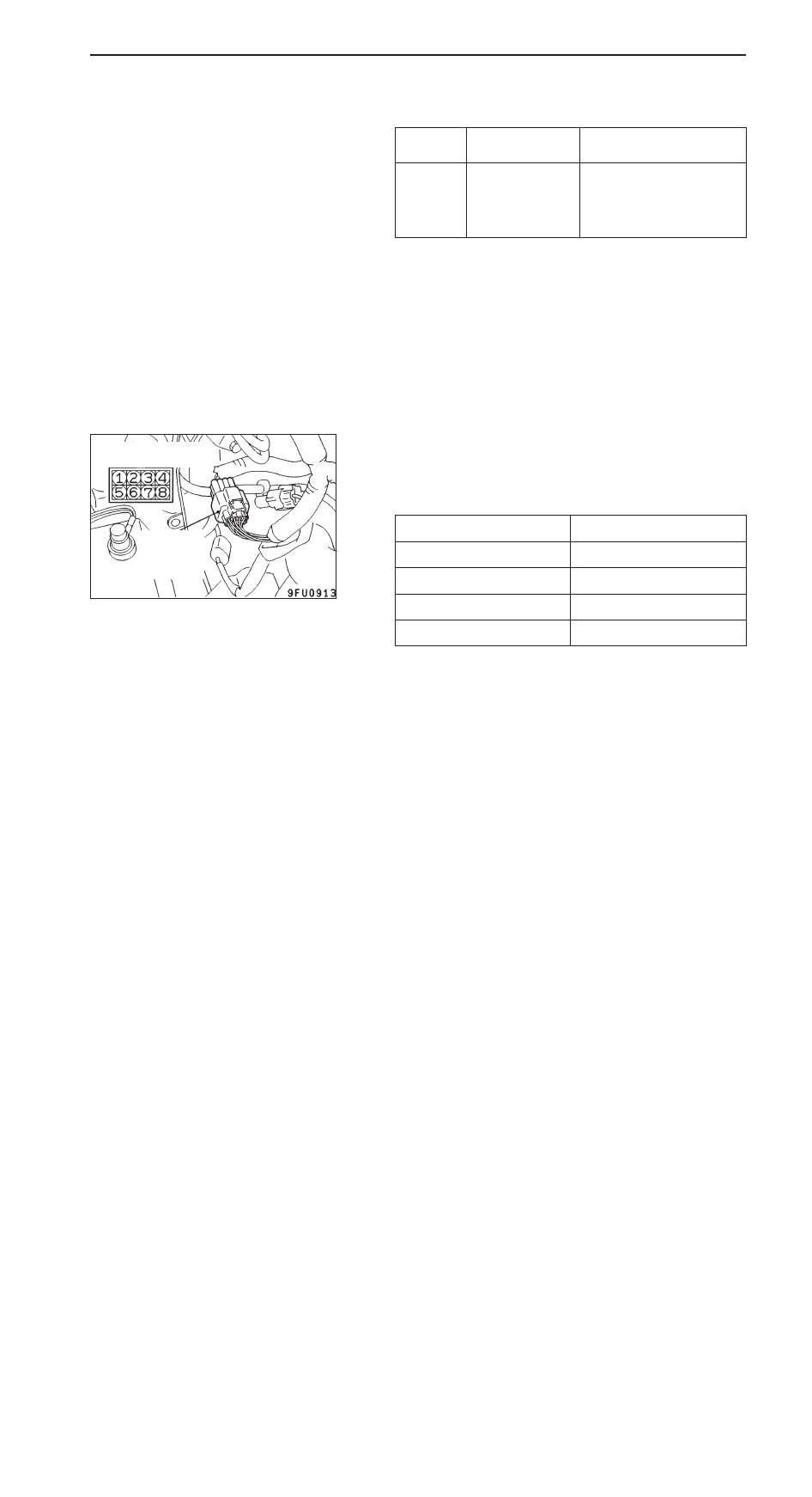
Disconnect the injector intermediate harness connector.

2.

Measure the resistance between each of the terminals.

Standard value: 0.9 – 1.1 

 (at 20

_

C)

Injector

Measurement terminal

No.1 cylinder

1 – 2

No.2 cylinder

3 – 4

No.3 cylinder

5 – 6

No.4 cylinder

7 – 8

3.

Connect the injector intermediate harness connector.

Injector side connec-
tor

Injector
intermediate
harness
connector

GDI – 

On-vehicle Service

13A-107

THROTTLE VALVE CONTROL SERVO CHECK

Operation Check

1.

Disconnect the air intake hose from the throttle body.

2.

Turn on the ignition switch.

3.

Check that the throttle valve opens or closes in response
to the accelerator pedal depression.

Check of Coil Resistance

1.

Disconnect the throttle valve control servo connector.

2.

Measure resistance between the throttle valve control
servo connector terminals.

Standard value:

Terminals to be measured

Resistance value (

)

1 – 3

1.35 – 1.65 (at 20

_

C)

2 – 4

3.

Check that there is no continuity between the terminals
and body.

PURGE CONTROL SOLENOID VALVE CHECK

Refer to GROUP 17 – Emission Control System.

EGR VALVE CHECK

Refer to GROUP 17 – Emission Control System.

Throttle valve
control servo

Equipment side
connector

GDI – 

Fuel Pump (High Pressure) and Fuel Pressure Regulator (High Pressure)

13A-108

FUEL PUMP (HIGH PRESSURE) AND FUEL PRESSURE
REGULATOR (HIGH PRESSURE)

REMOVAL AND INSTALLATION

Pre-removal and Post-installation Operation

D

Fuel Discharge Prevention <before removal only>
(Refer to P.13A-98.)

D

Engine Cover Removal and Installation

D

Resonance Tank Removal and Installation (Refer to
GROUP 15.)

D

Fuel Leak Check <after installation only> (Refer to
P.13A-98.)

O-ring

Engine oil

4

6

10

12

13

14

18

15

16

17

19

8

7

9

19 Nm

19 Nm

9 Nm

19 Nm

5 Nm

5 Nm 

 17

Nm

10 – 13
Nm

10 – 13
Nm

9 Nm

2, 7, 12,
18, 25

3

5

1

2

10 – 13
Nm

24 Nm

4

5

3

11

22

24

25

26

23

21

20

GDI – 

Fuel Pump (High Pressure) and Fuel Pressure Regulator (High Pressure)

13A-109

Fuel pump (High pressure) removal
steps

"

F

A D

Fuel pump (high pressure) air bleeding

D

Throttle body removal (Refer to
P.13A-113.)

A

A

"

1. Fuel pump protector

"

C

A

2. Fuel feed pipe

"

B

A

3. Back-up ring A

"

B

A

4. O-ring

"

B

A

5. Back-up ring B
6. Fuel pressure hose clamp

"

C

A

7. Fuel pressure hose connection
8. O-ring
9. Fuel return hose connection

"

E

A

10. Fuel pump (high pressure)

11. O-ring

12. Fuel pump return nipple
13. O-ring

Fuel pressure regulator (High
pressure) removal steps

D

Intake manifold assembly removal
(Refer to GROUP 15.)

14. Fuel pressure sensor connector 

connection

15. Fuel pressure sensor

"

D

A

16. O-ring

"

D

A

17. Back-up ring

"

C

A

18. Fuel return pipe

"

B

A

19. Back-up ring A

"

B

A

20. O-ring

"

B

A

21. Back-up ring B
22. Fuel return hose connection

"

A

A

23. Fuel pressure regulator (high 

pressure)

24. Spacer
25. Fuel nipple
26. O-ring

REMOVAL SERVICE POINT

A

A

"

FUEL PUMP PROTECTOR REMOVAL

Lift up the transmission with a jack to create clearance between
the engine and front deck, and then remove the fuel pump
protector.

INSTALLATION SERVICE POINTS

"

A

A

FUEL PRESSURE REGULATOR (HIGH
PRESSURE) INSTALLATION

1.

Install provisionally the fuel pressure regulator (high
pressure) to the spacer.

2.

Install the fuel return pipe, and then tighten the fuel pressure
regulator (high pressure) to the specified torque.

"

B

A

BACK-UP RING B/O-RING/BACK-UP RING A
INSTALLATION

Install the back-up rings and the O-ring as shown in the
illustration.

Caution
1.

Install the back-up ring B facing its cutaway surface
toward the opposite side of the O-ring as shown in
the illustration.

2.

Confirm the outer diameter of the back-up ring A. Take
care not to install the back-up ring for the fuel pressure
sensor by mistake. (Outer diameter of the back-up
ring A: 14.8 mm)

Cutaway
surface

Back-up ring A

O-ring

Back-up ring B


Content   ..  58  59  60  61   ..