Mitsubishi Pajero Pinin. Manual - part 3
GENERAL –
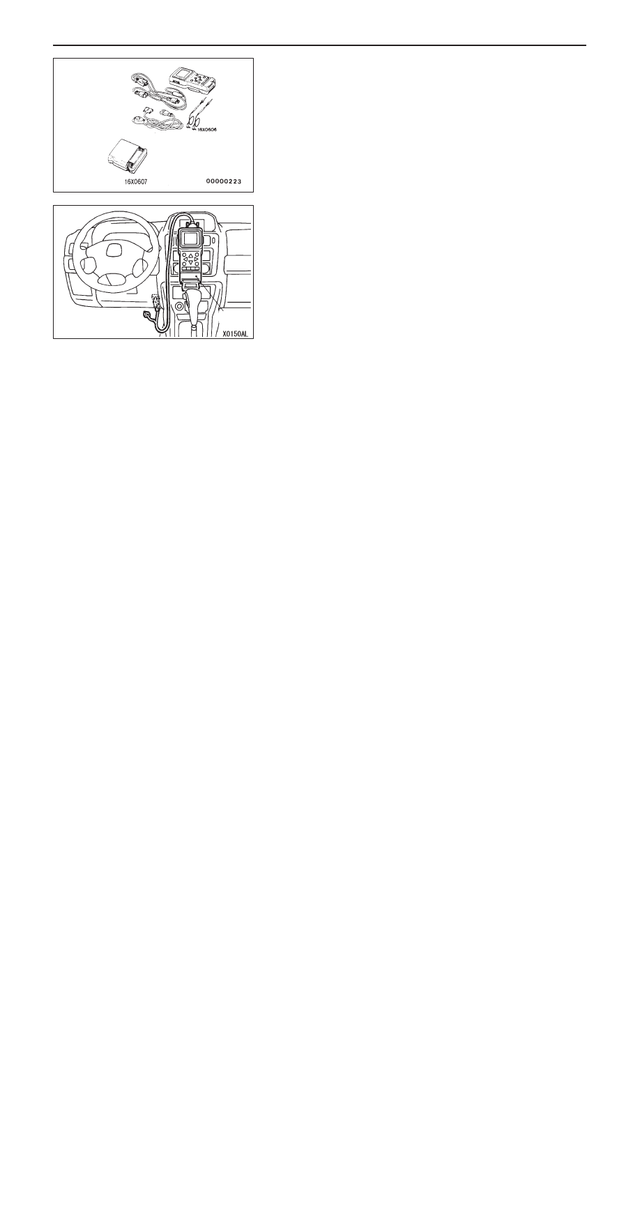
Precautions Before Service
00-19
MUT-
II
Refer to the “MUT-
II
REFERENCE MANUAL” or “MUT-
II
OPERATING INSTRUCTIONS” for instructions on handling
the MUT-
II
.
Connect the MUT-
II
to the diagnosis connector as shown in
the illustration.
Caution
Turn the ignition switch to the LOCK (OFF) position before
connecting or disconnecting the MUT-
II
.
IN ORDER TO PREVENT VEHICLES FROM FIRE
“Improper installation of electrical or fuel related parts could
cause a fire. In order to retain the high quality and safety
of the vehicle, it is important that any accessories that may
be fitted or modifications/repairs that may be carried out which
involve the electrical or fuel systems, MUST be carried out
in accordance with MMC’s information/Instructions”.
ENGINE OILS
Health Warning
Prolonged and repeated contact with mineral oil will result
in the removal of natural fats from the skin, leading to dryness,
irritation and dermatitis. In addition, used engine oil contains
potentially harmful contaminants which may cause skin cancer.
Adequate means of skin protection and washing facilities must
be provided.
Recommended Precautions
The most effective precaution is to adapt working practices
which prevent, as far as practicable, the risk of skin contact
with mineral oils, for example by using enclosed systems for
handling used engine oil and by degreasing components,
where practicable, before handling them.
MUT-
II
sub-assembly
ROM pack
MUT-
II