Mitsubishi Lancer. Manual - part 247
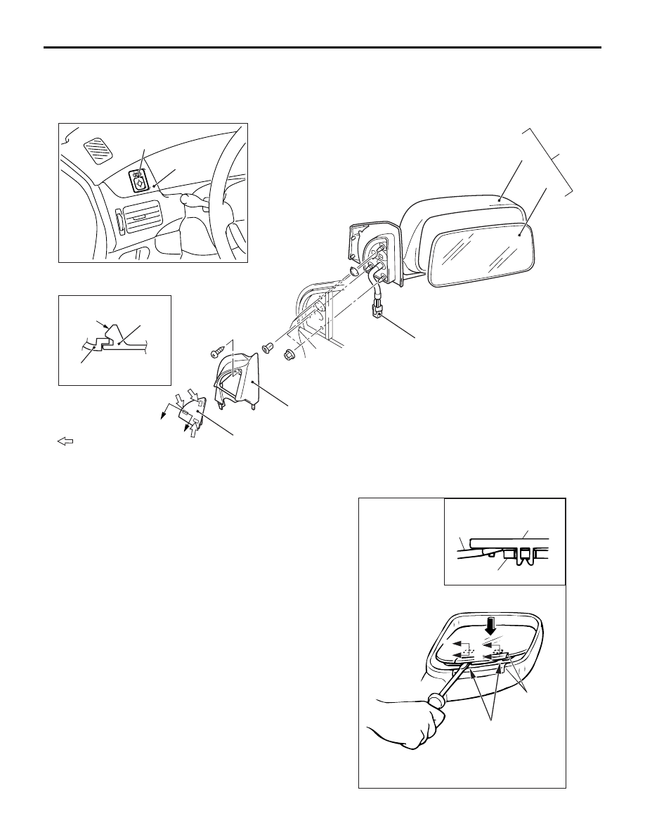
DOOR MIRROR
EXTERIOR
51-50
DOOR MIRROR
REMOVAL AND INSTALLATION
M1511006400308
AC304733
Note
: Claw positions
AB
A
A
Section A – A
Claw
1
2
1
2
3
4
5
6
7
8
Door mirror removal steps
1. Cover
2. Delta inner cover
3. Harness connector <Vehicles with
remote controlled mirror>
4. Door mirror assembly
5. Door mirror body assembly
<<
A
>> >>
A
<< 6. Mirror
Remote controlled mirror switch
removal steps
7. Instrument panel ornament (Refer to
GROUP 52A, Instrument panel
8. Remote controlled mirror switch
REMOVAL SERVICE POINT
<<A>> MIRROR REMOVAL
AC000441
00007256
Mirror
Flat-tipped
screwdriver
Section A – A
Pivot plate
Notch
Protective
tape
A
A
A
A
AE