Mitsubishi Lancer. Manual - part 248
GENERAL INFORMATION
WHEEL AND TYRE
31-2
GENERAL INFORMATION
M1311000100350
The wheels and tyres of the following specifications
have been established.
SPECIFICATIONS
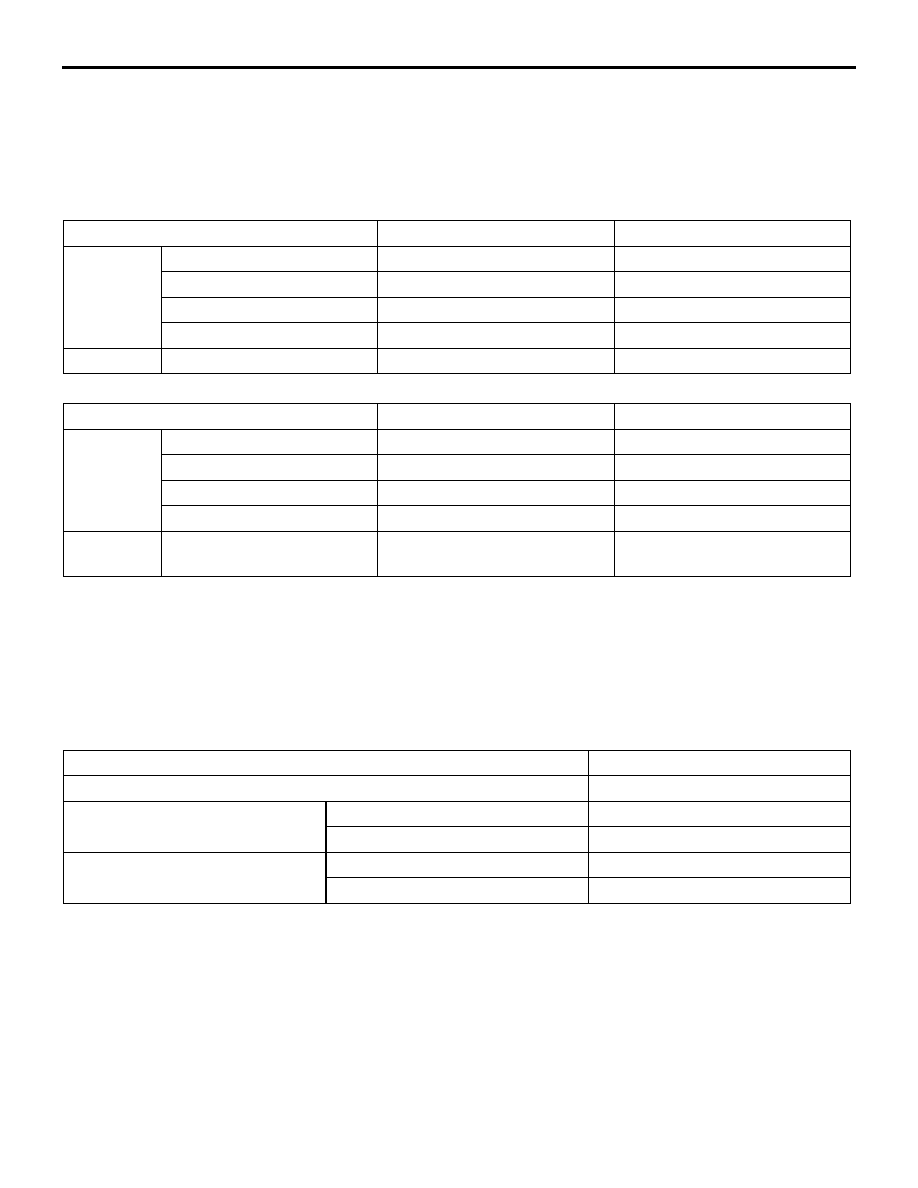
ROAD WHEEL AND TYRE
Item
Invite
Intense
Wheel
Type
Steel type or Aluminium type*
Aluminium type
Size
15
× 6JJ
16
× 6JJ
Amount of wheel offset mm 46
46
PCD mm
114.3
114.3
Tyre
Size
195/60R15 88H
195/50R16 84V
SPARE WHEEL AND TYRE
Item
Invite
Intense
Spare
wheel
Type
Steel type
Steel type
Size
16
× 4T or 15 × 6JJ*
16
× 4T or 16 × 6JJ*
Amount of wheel offset mm 46
40 or 46*
PCD mm
114.3
114.3
Spare tyre
Size
T125/70D16 96M or
195/60R15 88H*
T125/70D16 96M or
195/50R16 84V*
NOTE:
.
•
The * mark indicates optional item.
•
PCD (Pitch Circle Diameter) indicates the pitch circle diameter of the wheel installation holes.
SERVICE SPECIFICATIONS
M1311000300398
Item
Limit
Tread depth of tyre mm
Minimum 1.6
Wheel runout
<Aluminium wheel>
Radial runout mm
1.0 or less
Lateral runout mm
1.0 or less
Wheel runout
<Steel wheel>
Radial runout mm
1.2 or less
Lateral runout mm
1.2 or less