Mitsubishi Lancer (4A9 engine). Manual - part 36
AC700096
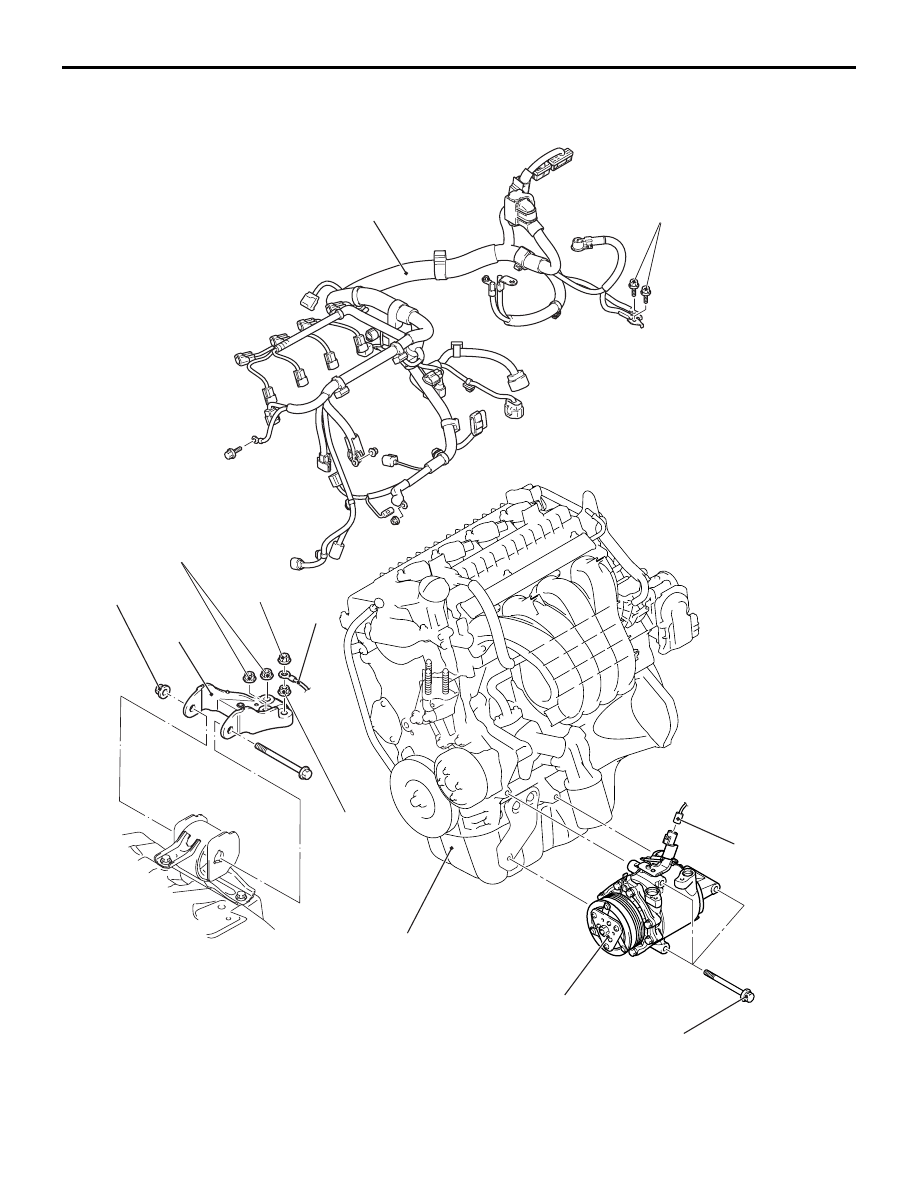
7
8
6
11
9
10
23 ± 6 N·m
AC
66 ± 7 N·m
13 ± 2 N·m
100 ± 5 N·m
66 ± 7 N·m
9.0 ± 2.0 N·m
ENGINE ASSEMBLY
ENGINE MECHANICAL <4A9>
11A-58
|
|
|
AC700096 7 8 6 11 9 10 23 ± 6 N·m AC 66 ± 7 N·m 13 ± 2 N·m 100 ± 5 N·m 66 ± 7 N·m 9.0 ± 2.0 N·m ENGINE ASSEMBLY ENGINE MECHANICAL <4A9> 11A-58 |