Mitsubishi Lancer (4A9 engine). Manual - part 35


  Index      Mitsubishi     Mitsubishi Lancer (4A9 engine) 12GS41 & 44S - service repair manual


Search            


Content   ..  33  34  35  36   ..


Mitsubishi Lancer (4A9 engine). Manual - part 35


ACA00941

A

ACA00941AB

R7 ± 0.5 mm

5 ± 0.5 mm

Ø2 ± 0.5 mm

E-E

R8.5 ± 0.5 mm

Ø2 ± 0.5 mm

D-D

3 ± 0.5 mm

Ø2 ± 0.5 mm

F-F

R

R

H

R

R

15 mm

S-S

S

S

S

R-R

Ø2 ± 0.5 mm

G

C

C

C

C

G A

A

D

B

B

A

A

B

B

D

D

D

E

E

E

E

B

F

F

F

G

G

H

A

A

U

4.5 ± 0.5 mm

Ø1.75 ± 0.5 mm

C-C

3 ± 0.5 mm

Ø1.75 ± 0.5 mm

B-B

Ø1.75 ± 0.5 mm

A-A

Ø2 ± 0.5 mm

3 ± 0.5 mm

P

P

P

P

G

22 mm

6.1 mm

Ø2 ± 0.5 mm

Q

Q

P-P

Q-Q

U

V

V

V-V

W

S

W

W-W

6 mm

1 mm

1 mm

Ø1.75 ± 0.5 mm

A

B

TIMING CHAIN

ENGINE MECHANICAL <4A9>

11A-54

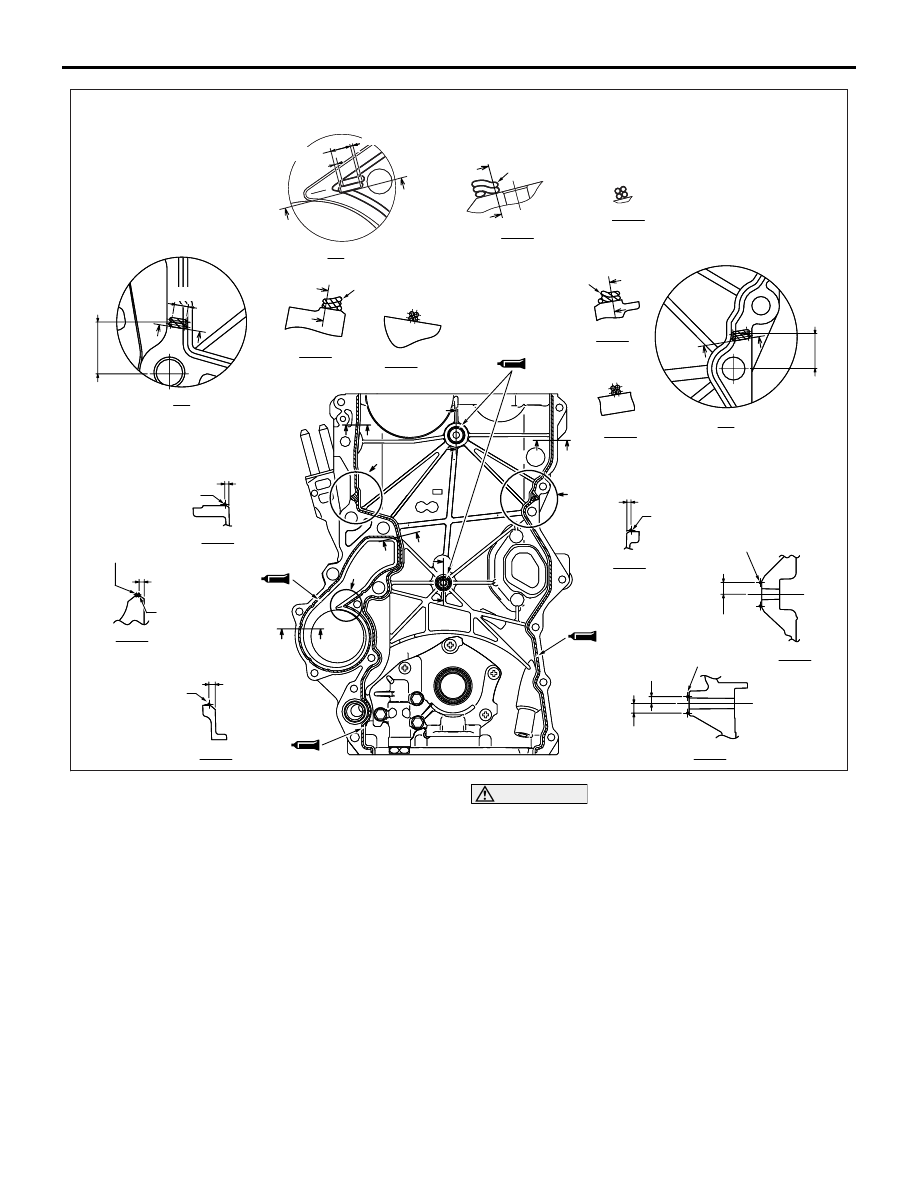
3. Apply a bead of the sealant to the cylinder block 

and cylinder head mating surface of the timing 
chain case assembly as shown.

Specified sealant:

A: ThreBond 1217G or equivalent
B: ThreBond 1217D or equivalent
NOTE: Install the timing chain case assembly 
immediately after applying sealant.

CAUTION

• If the sealant contacts any other part during 

installation of the timing chain case assembly, 
apply sealant again before installing the tim-
ing chain case assembly.

• After the installation, until a sufficient period 

of time (one hour or more) elapses, do not 
apply the engine oil or water to the sealant 
application area or start the engine.

4. Taking care not to scrub the specified sealant 

applied on the timing chain case assembly with 
the cylinder block etc., install the timing chain 
case assembly to the cylinder block.

ACA00823

AC

Timing chain case assembly

A

A

A

A

A

A

A

B

B

B

C

C

D

D

E

E

TIMING CHAIN

ENGINE MECHANICAL <4A9>

11A-55

5. Install the timing chain case assembly mounting 

bolts to the position shown, and tighten the bolts 
to the specified torque.

Bolt 
(symbol)

Diameter 

× length 

mm

Tightening torque 
N

⋅m

A

× 25

9.5 

± 2.5

B

× 30

9.5 

± 2.5

C

× 45

9.5 

± 2.5

D

10 

× 50

42 

± 16

E

10 

× 90

42 

± 16

>>D<< O-RING/WATER PUMP ASSEMBLY 
INSTALLATION
1. Carefully remove the drying material and other 

foreign materials on the installation groove for the 
water pump O-ring.

2. Carefully remove the drying material and other 

foreign materials on the water pump installation 
area of the timing chain case assembly.

3. Sufficiently apply water or coolant to the O-ring to 

prevent it from dropping using brushes.

ACA00858AB

Flange

O-ring groove

4. Securely fit the O-ring flange area into the 

installation groove of the water pump O-ring.

5. Reverse the water pump carefully and check that 

the O-ring does not fall down.

CAUTION

When installing the water pump, pay attention 
not to let the O-ring fall down or be bitten. Other-
wise, a coolant leak may be caused.
6. Install the water pump to the timing chain case 

assembly.
NOTE: The water pump assembly mounting bolts 
are also used for the timing chain case assembly. 
Thus install the water pump assembly together 
with the timing chain case assembly, or else 
immediately after installing the timing chain case 
assembly.

>>E<< CRANKSHAFT FRONT OIL SEAL 
INSTALLATION

AC311773

AB

MB990699

(Engine oil)

Oil seal

MB991993

Crankshaft

1. Apply a small amount of engine oil to the outer 

circumference of special tool crankshaft front oil 
seal guide (MB991993) and install it to the 
crankshaft.

2. Apply a small amount of engine oil to the entire 

inner circumference of the oil seal lip.

CAUTION

When installing the crankshaft front oil seal, be 
careful to avoid damage to the crankshaft front 
oil seal.
3. Using special tool differential oil seal installer 

(MB990699), drive the oil seal so that it is flush 
with the timing chain case assembly.

ENGINE ASSEMBLY

ENGINE MECHANICAL <4A9>

11A-56

ENGINE ASSEMBLY

REMOVAL AND INSTALLATION

M1112001006869

CAUTION

• When the engine assembly replacement is performed, use the M.U.T.-III to initialise the learning 

value (Refer to GROUP 00 

 Precautions Before Service, Initialisation Procedure for Learning 

Value in MPI Engine ).

Pre-removal operation
• Hood Removal (Refer to GROUP 42A − Hood ).

• Fuel Line Pressure Reduction (Refer to GROUP 13A − 

On-vehicle Service, How to Reduce Pressurized Fuel 

Lines ).

• Engine Room Under Cover Front B and Engine Room 

Side Cover Removal (Refer to GROUP 51 

− Under Cover 

).

• Engine Coolant Draining (Refer to GROUP 14 − On-vehi-

cle Service, Engine Coolant Replacement ).

• Engine Oil Draining (Refer to GROUP 12 − On-vehicle 

Service, Engine Oil Replacement ).

• Transmission Oil Draining (Refer to GROUP 22A − On-

vehicle Service, Transmission Oil Change ) <M/T>.

• Automatic Transmission Fluid Draining (Refer to GROUP 

23C 

− On-vehicle Service, Automatic Transmission Fluid 

Change ) <A/T>.

• Engine Cover Removal (Refer to ).

• Air Cleaner Intake Hose and Air Cleaner Assembly 

Removal (Refer to GROUP 15 

− Air Cleaner  ).

• Battery and Battery Tray Removal (Refer to GROUP 54A 

− Battery ).

• Engine-ECU Removal (Refer to GROUP 13A − Engine-

ECU ).

• Radiator Removal (Refer to GROUP 14 − Radiator ).
• Drive Belt Removal (Refer to ).

• Alternator and Alternator Brace Removal (Refer to 

GROUP 16 

− Charging System, Alternator Assembly ).

Post-installation operation
• Alternator and Alternator Brace Installation (Refer to 

GROUP 16 

− Charging System, Alternator Assembly ).

• Drive Belt Installation (Refer to ).

• Radiator Installation (Refer to GROUP 14 − Radiator ).

• Engine-ECU Installation (Refer to GROUP 13A − Engine-

ECU ).

• Battery and Battery Tray Installation (Refer to GROUP 

54A 

− Battery ).

• Air Cleaner Intake Hose and Air Cleaner Assembly Instal-

lation (Refer to GROUP 15 

− Air Cleaner ).

• Transmission Oil Refilling (Refer to GROUP 22A − On-

vehicle Service, Transmission Oil Change ) <M/T>.

• Automatic Transmission Fluid Refilling (Refer to GROUP 

23C 

− On-vehicle Service, Automatic Transmission Fluid 

Change ) <A/T>.

• Engine Oil Refilling (Refer to GROUP 12 − On-vehicle 

Service, Engine Oil Replacement ).

• Engine Coolant Refilling (Refer to GROUP 14 − On-vehi-

cle Service, Engine Coolant Replacement ).

• Drive Belt Tension Check (Refer to ).

• Engine Cover Installation (Refer to ).
• Engine Room Under Cover Front B and Engine Room 

Side Cover Installation (Refer to GROUP 51 

− Under 

Cover ).

• Fuel Leak Check
• Hood Installation (Refer to GROUP 42A − Hood ).

AC700100AB

1

5

3

4

2

Removal steps 

1.

Brake booster vacuum hose 
connection

2.

Purge solenoid hose connection

<<

A

>>

>>

C

<<

3.

Fuel high-pressure hose 
connection

4.

Heater hose connection

5.

Water hose connection

ENGINE ASSEMBLY

ENGINE MECHANICAL <4A9>

11A-57

Removal steps (Continued)


Content   ..  33  34  35  36   ..