Mitsubishi Lancer (4A9 engine). Manual - part 34
Removal steps
1.
Earth cable connection
<<
A
>>
•
A/C compressor and clutch
assembly.
<<
B
>>
•
Engine and transmission assembly
supporting
•
Engine mounting bracket (Refer to
GROUP 32
− Engine Mounting )
2.
Alternator brace
>>
E
3.
Crankshaft front oil seal
>>
D
<<
4.
Water pump assembly
>>
D
<<
5.
O-ring
>>
C
<<
6.
Timing chain case assembly
>>
C
<<
7.
O-ring
>>
B
<<
8.
Timing chain tensioner cover
<<
C
>>
>>
A
<<
9.
Timing chain tensioner
>>
A
<<
10. Tensioner lever assembly
>>
A
<<
11. Timing chain guide
>>
A
<<
12. Timing chain
TIMING CHAIN
ENGINE MECHANICAL <4A9>
11A-50
REMOVAL SERVICE POINTS
<<A>> A/C COMPRESSOR AND CLUTCH
ASSEMBLY REMOVAL
1. Remove the A/C compressor and clutch assembly
together with the hose from the bracket.
2. Tie the removed A/C compressor and clutch
assembly with a string at a position where it will
not interfere with the removal and installation of
timing chain case assembly.
<<B>> ENGINE AND TRANSMISSION ASSEMBLY
HOLDING
Install a special tool for holding the engine and trans-
mission assembly.
1. <When special tool engine hanger (MB991928) is
used>
(1) Assemble special tool engine hanger
(MB991928) (Set the following parts on the
base hanger).
• Slide bracket (HI)
• Foot x 4 (standard) (MB991932)
•
AC611565AC
MB991932
MB991932
MB991930
Joint x 2 (90) (MB991930)
(2) Set the foot of the special tool as shown in the
figure.
NOTE: Slide the slide bracket (HI) to adjust the
engine hanger balance.
AC700024AB
MB991454
MB991928
MB991527
(3) Install special tool engine hanger (MB991527)
and special tool engine hanger balancer
(MB991454) to the engine hanger, and set it to
special tool MB991928 to support the engine
and transmission assembly.
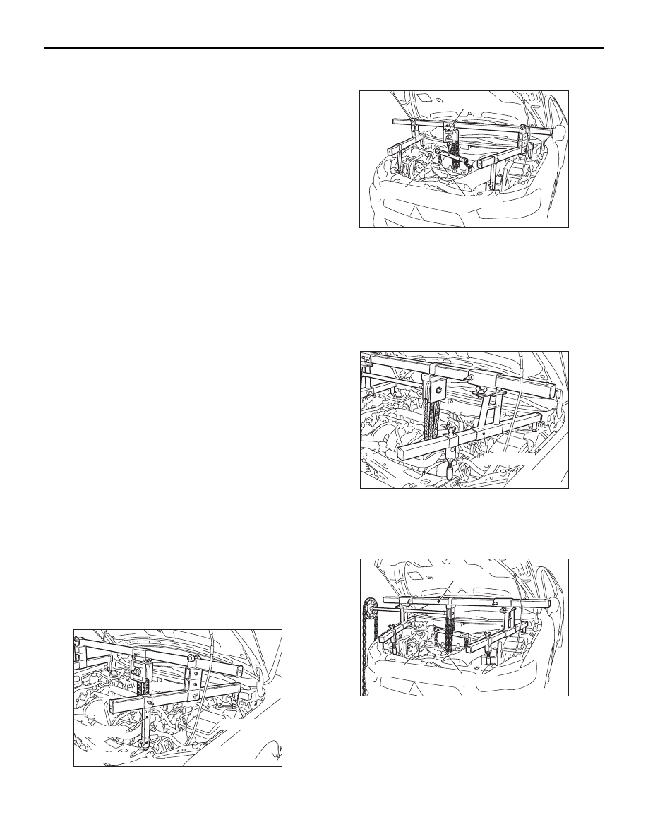
2. <When special tool engine hanger (MB991895) is
used>
AC611564AC
MB991895
(1) Set the foot of special tool engine hanger
(MB991895) as shown in the figure.
NOTE: Slide the foot to adjust the engine
hanger balance.
AC700023AB
MB991454
MB991895
MB991527
(2) Install special tool engine hanger (MB991527)
and special tool engine hanger balancer
(MB991454) to the engine hanger, and set it to
special tool MB991895 to support the engine
and transmission assembly.