Mitsubishi Evolution X. Manual - part 849


  Index      Mitsubishi     Mitsubishi Evolution X - service repair manual 2008 year


Search            


Content   ..  847  848  849  850   ..


Mitsubishi Evolution X. Manual - part 849


DOOR MIRROR

TSB Revision

EXTERIOR

51-79

CAUTION

When attaching the marks, the ambient temperature 
should be 20 

 38° C (68  100° F) and the air should be 

completely free of dust. If the ambient temperature is lower 
than 20

° C (60° F), the marks and the places on the vehicle 

body where the marks are to be attached should be heated 
to 20 

 30° C (68  86° F).

(2) Peel off the protection sheet on the back of the marks to 

affix it in position.
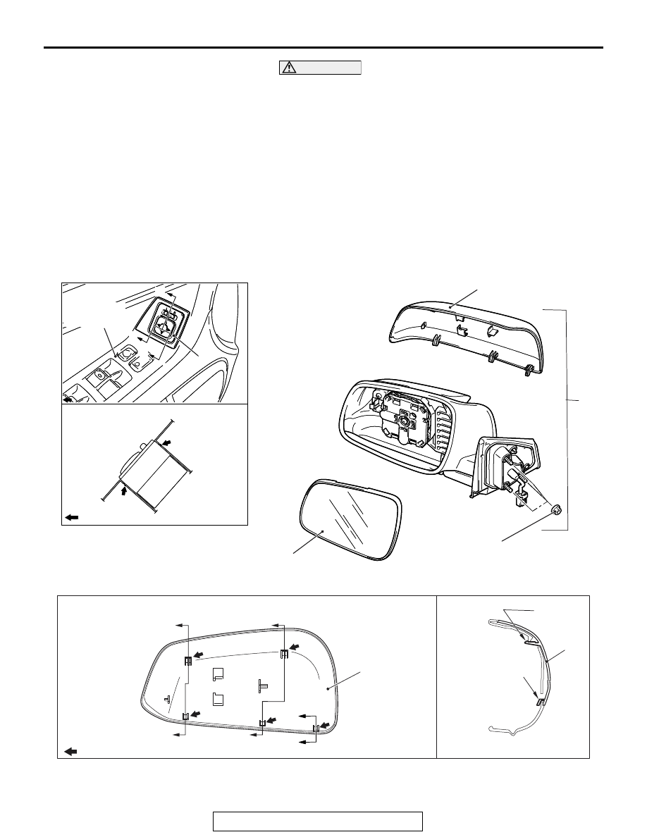
DOOR MIRROR

REMOVAL AND INSTALLATION

M1511006400933

AC607955

AC607955

3

AB

A

Section A – A

Power window 
switch panel

: Claw positions

A

A

4

1

2

5.0 ± 2.0 N·m
45 ± 17 in-lb

AC705416

3

AD

3

Claw

B

Section B – B

Door mirror outer cover claw positions

: Claw positions

B

B

B

Claw

B

B

DOOR MIRROR

TSB Revision

EXTERIOR

51-80

REMOVAL SERVICE POINT

.

<<A>> DOOR MIRROR OUTER COVER REMOVAL

CAUTION

The claws of the mirror are prone to break when working in 
cold temperatures. Always use a hair drier or the like to 
warm up the mirror claws and its periphery to 20

° C or 

higher prior to works. When the mirror is heated too 
quickly from its cold state, it may be broken.
1. Slant the mirror upward with your hands. Then insert a 

flat-tipped screwdriver wrapped with protective tape 
between the pivot plate and mirror through the cut-out from 
behind the mirror. Now pry off the mirror claws and release 
the lower side of the mirror as shown in the illustration.

2. Release the upper side of the mirror from the tabs while 

pulling out the mirror downwards.

Door mirror assembly removal 
steps 

Tweeter (Refer to GROUP 54A, 
Speaker 

P.54A-575

)

Door mirror connector connection

1.

Door mirror assembly

Door mirror outer cover removal 
steps 

2.

Mirror

<<A>>

>>A<<

3.

Door mirror outer cover
Remote controlled mirror switch 
removal steps 

Front door trim (Refer to GROUP 
52A, Door Trim 

P.52A-15

)

4.

Remote controlled mirror switch

AC605127

A

A

AC

Section A – A

Claw positions

Claws

Claw

Claw

Pivot plate

Mirror

Mirror

Flat-tipped screwdriver

Flat-tipped screwdriver

Flat-tipped screwdriver

Protective tape

DOOR MIRROR

TSB Revision

EXTERIOR

51-81

3. Remove the door mirror outer cover by disengaging the 

claws in the numerical order of the illustration from the mirror 
body side.

INSTALLATION SERVICE POINT

.

>>A<< DOOR MIRROR OUTER COVER INSTAL-
LATION

CAUTION

Tap the claw positions securely to confirm that they are 
engaged securely.
Install the door mirror outer cover by engaging the claws in the 
numerical order of the illustration.

INSPECTION

M1511006500554

REMOTE CONTROLLED MIRROR OPERATION 
CHECK

Check that the mirror moves as described in the table when 
each terminal is connected to the battery.

AC608686AB

2

1

2

: Claw positions

2

1

AC608686AC

2

1

2

1

1

: Claw positions

Battery connection

Direction 
operation

• Connect terminal 8 to the negative 

battery terminal.

• Connect terminal 6 to the positive battery 

terminal.

Up

• Connect terminal 8 to the positive battery 

terminal.

• Connect terminal 6 to the negative 

battery terminal.

Down

• Connect terminal 8 to the negative 

battery terminal.

• Connect terminal 7 to the positive battery 

terminal.

Right

AC608725AB

DOOR MIRROR

TSB Revision

EXTERIOR

51-82

DOOR MIRROR CONTROL SWITCH CONTINUITY 
CHECK

• Connect terminal 8 to the positive battery 

terminal.

• Connect terminal 7 to the negative 

battery terminal.

Left

Battery connection

Direction 
operation

Switch 
position

Tester connection

Specified 
condition

OFF

− 2, 9 − 3, 9 − 6, 9 − 10, 

− 11, 1 − 2,1 − 3, 1 − 6, 

−10, 1 − 11

Open circuit

Left 
side

OFF

− 6, 9 − 10, 9 − 11,

 1 

− 6, 1 − 10, 1 − 11

Open circuit

Up

− 6, 9 − 11

Continuity 
exists (2 

Ω or 

less)

Down 1 

− 11, 6 − 9

Right

− 6, 9 − 10

Left

− 10, 6 − 9

Right 
side

OFF

− 2, 9 − 3, 9 − 6, 

− 2, 1 − 3, 1 − 6

Open circuit

Up

− 6, 3 − 9

Continuity 
exists (2 

Ω or 

less)

Down 1 

− 3, 6 − 9

Right

− 6, 2 − 9

Left

− 2, 6 − 9

AC406691

2

1

4

3

5

10

9

8

7

6

11


Content   ..  847  848  849  850   ..