Mitsubishi Evolution X. Manual - part 833


  Index      Mitsubishi     Mitsubishi Evolution X - service repair manual 2008 year


Search            


Content   ..  831  832  833  834   ..


Mitsubishi Evolution X. Manual - part 833


SIDE AIR DAM

TSB Revision

EXTERIOR

51-15

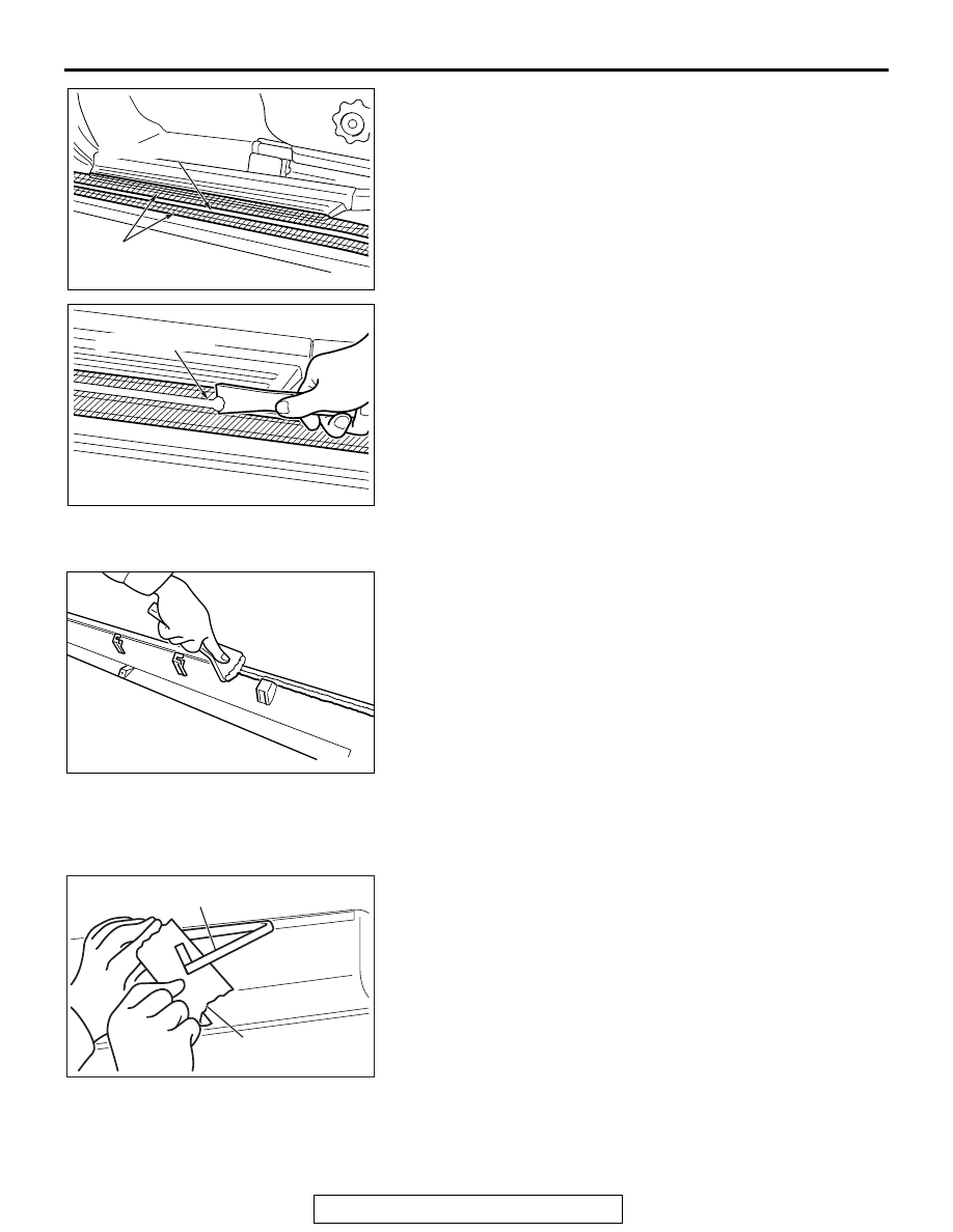
(1) Attach protection tape all the way along the edges of the 

double-sided tape which is still adhering to the body. 

(2) Scrape off the double-sided tape with a resin spatula as 

possible.

(3) Peel off the protection tape.
(4) Use a shop towel moistened with 3M

™ AAD Part number 

8906 or equivalent to wipe the body.

2. Remove double-sided tape remaining on side air dam and 

adhere double-sided tape (when re-using side air dam). 

(1) Scrape off the double-sided tape on the side air dam with 

a resin spatula as much as possible.

(2) Wipe the side air dam surface and clean it with a rag 

moistened with isopropyl alcohol.

(3) Remove only a small amount of the residual adhesive.
(4) Apply the primer as specified on the residual adhesive.
(5) Adhere the double-sided tape as specified on the side air 

dam.

INSTALLATION SERVICE POINT

.

>>A<< SIDE AIR DAM INSTALLATION

1. Tear off the double-sided tape backing paper.

NOTE: Attach the adhesive tape to the edge of the backing 
paper makes the backing paper tear off easier.

2. Install the side air dam.

NOTE: If the double-sided tape is difficult to affix in cold tem-
perature, etc., warm the bonding surfaces of the body and 
side air dam to about 40 

 60

°

C (104 

 140

°

F) before affix-

ing the tape.

3. Firmly press in the side air dam.

AC200049

AC

Protection tape

Double-sided tape

AC200050

AC

Double-sided tape

AC103187

AC103247

Backing paper

Adhesive tape

AE

UNDER COVER

TSB Revision

EXTERIOR

51-16

UNDER COVER

REMOVAL AND INSTALLATION

M1511019600443

AC704710

5

6

7

6

AB

2

1

A

A

4

1

1

2

B

3

Bolt

Front end crossmember

Air dam 
skirt panel

Clip (a)

Clip (a)

Section A – A

3.5 ± 1.5 N·m
31 ± 13 in-lb

3.5 ± 1.5 N·m
31 ± 13 in-lb

3.5 ± 1.5 N·m
31 ± 13 in-lb

AC705190AB

1

1

2

: Clip (a)

: Bolt

: Clip (b)

View B (Bolt and clip positions)

REAR SPOILER

TSB Revision

EXTERIOR

51-17

REAR SPOILER

REMOVAL AND INSTALLATION

M1511006100318

Removal steps 

1.

Engine room under cover front A

2.

Engine room under cover center

3.

Engine room under cover front B 
assembly

4.

Engine room under cover extension

5.

Engine room under cover front B

6.

Engine room side cover

7.

Front floor under cover

Removal steps (Continued)

AC708776

<MR>

AD

3

1

1

4

2

2

2

4

2

A

B

B

C

C

Claw

Claw

Claw

Section B – B

View A

Section C – C

8.5 ± 1.5 N·m
76 ± 13 in-lb

8.5 ± 1.5 N·m
76 ± 13 in-lb

8.5 ± 1.5 N·m
76 ± 13 in-lb

8.5 ± 1.5 N·m
76 ± 13 in-lb

Removal steps 

1. Nut
2. Cap

3. Rear spoiler assembly
4. Grommet

Removal steps (Continued)

REAR SPOILER

TSB Revision

EXTERIOR

51-18

INSTALLATION SERVICE POINT

.

>>A<< TAPE INSTALLATION

1.  Installation position

CAUTION

• The ambient temperature should be 15 (59) to 

40

° C(104° F). Ensure that the working area is clean.

• If ambient temperature is less than 15° C (59° F), heat the 

tape and application surface to a temperature of 15 (59) 
to 40

° C (104° F).

• Be careful that air bubbles are not formed under the 

tape.

2. Installation procedure

(1) Wipe the tape application surface and clean it with a rag 

moistened with isopropyl alcohol.

(2) Remove backing paper from the tape, and apply it to the 

rear spoiler assembly.

AC705243 AE

2

1

3

3

1

4

4

5.0 ± 1.0 N·m
44 ± 9 in-lb

5.0 ± 1.0 N·m
44 ± 9 in-lb

5.0 ± 1.0 N·m
44 ± 9 in-lb

5.0 ± 1.0 N·m
44 ± 9 in-lb

<GSR>

Removal steps 

1. Nut
2. Rear spoiler assembly

3. Grommet

>>

A

<< 4. Tape

Removal steps (Continued)

AC609932

Tape

AB

Rear spoiler
assembly


Content   ..  831  832  833  834   ..