Mitsubishi Evolution X. Manual - part 312
VEHICLE IDENTIFICATION
TSB Revision
GENERAL
00-23
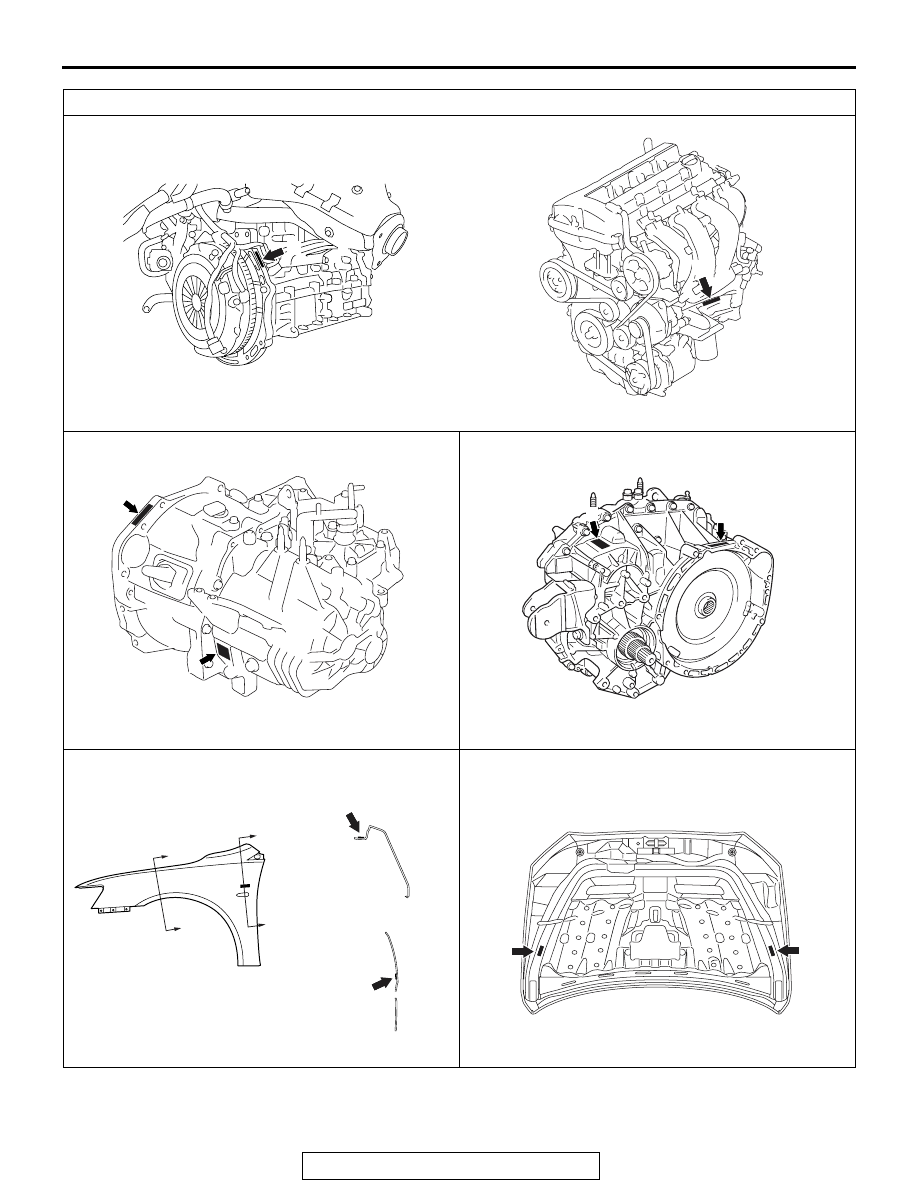
Label area (x: for original equipment parts, y: for replacement parts)
AC609841
Engine
AB
x
AC612304AB
y
AC708134
x
y
AB
Manual transaxle (M/T)
AC707965
x
AB
Twin clutch sportronic shift transmission (TC-SST)
y
b
b
a
a
x
y
AC608723
View A (Front fender)
The illustration indicates left outer side.
Right side is symmetrically opposite.
Section a - a
Section b - b
AB
AC708456
AC708344
View B (Hood)
x
y
AB