Mitsubishi Evolution X. Manual - part 22
THEFT PROTECTION
TSB Revision
BODY CONSTRUCTION
1-31
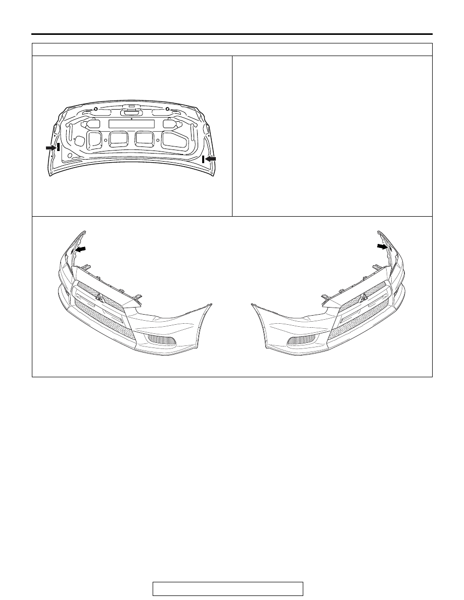
Label area (x: for original equipment parts, y: for replacement parts)
AC612302
View C (Trunk lid)
x
y
AB
AC710511
x
AB
View D (Front bumper)
AC710513
View D'
y