Mitsubishi Lancer Evolution X. Manual - part 475
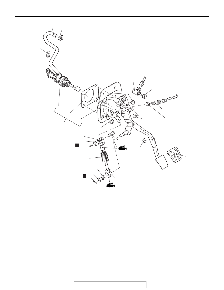
CLUTCH PEDAL AND MASTER CYLINDER
TSB Revision
CLUTCH
21A-5
AC709620
1
9
7
8
12
3
3
2
4
5
11
12 ± 3 N·m
107 ± 26 in-lb
15 ± 3 N·m
11 ± 2 ft-lb
AB
13
10
13
14
14
19
18
17
16
6
12 ± 3 N·m
107 ± 26 in-lb
N
N
15
Removal steps
>>
C
1.
Clutch switch
>>
B
2.
Clutch interlock switch
3.
Stopper
4.
Reservoir hose and brake
fluid reservoir connection
5.
Hose clip
<<
A
>>
>>
A
6.
Clutch tube assembly A
connection
7.
Clutch master cylinder and
clutch pedal assembly
<<
B
>>
8.
Clutch master cylinder
9.
Clutch pedal assembly
10. Sealer
11. Pedal pad
12. Stopper
13. Sprit pin
14. Washer
15. Clevis pin
16. Rod A
17. Turn over spring
18. Rod B
19. Bush
Removal steps