Mitsubishi Lancer Evolution X. Manual - part 476
CLUTCH CONTROL
TSB Revision
CLUTCH
21A-9
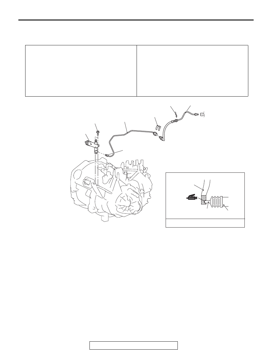
CLUTCH CONTROL
REMOVAL AND INSTALLATION
M1211001901225
Pre-removal Operation
• Strut Tower Bar Removal (Refer to GROUP 42A, Strut
Tower Bar
).
• Air Cleaner Assembly Removal (Refer to GROUP 15, Air
Cleaner
• Engine Control Harness Connector Bracket Removal
(Refer to GROUP 54A, Battery
.)
• Clutch Fluid Draining
Post-installation Operation
• Engine Control Harness Connector Bracket Installation
(Refer to GROUP 54A, Battery
.)
• Air Cleaner Assembly Installation (Refer to GROUP 15,
Air Cleaner
• Strut Tower Bar Installation (Refer to GROUP 42A, Strut
Tower Bar
).
• Clutch Fluid Supplying
• Clutch Line Bleeding (Refer to
• Clutch Pedal Check (Refer to
AC709624
Release fork
7
Release cylinder
push rod
MITSUBISHI Part No.0101011 or equivalent
AD
1
4
5
2
3
15 ± 1 N·m
11 ± 1 ft-lb
24 ± 4 N·m
18 ± 3 ft-lb
Clutch line removal steps
•
Air cleaner assembly (Refer
to GROUP 15, Air Cleaner
1.
Hose clip B
<<
A
>>
>>
A
2.
Clutch tube assembly A
3.
Hose clip A
<<
A
>>
>>
A
4.
Clutch tube assembly B
Clutch release cylinder
removal steps
•
Air cleaner element, air
cleaner intake duct, air
cleaner body, air cleaner
bracket (Refer to GROUP
15, Air Cleaner
.)
5.
Clutch release cylinder