Mitsubishi Lancer Evolution X. Manual - part 70


  Index      Mitsubishi     Mitsubishi Lancer Evolution X GS41EVO - service repair manual 2008 year


Search            


Content   ..  68  69  70  71   ..


Mitsubishi Lancer Evolution X. Manual - part 70


CAMSHAFT

TSB Revision

ENGINE MECHANICAL

11A-33

<<H>> POWER STEERING OIL PUMP ASSEMBLY 
REMOVAL

1. With the hose installed, remove the power steering oil pump 

assembly from the bracket.

2. Tie the removed power steering oil pump assembly with a 

string at a position where it will not interfere with the removal 
and installation of oil control valve.

.

<<I>> OIL FEEDER CONTROL VALVE REMOVAL

CAUTION

After removal of the oil feeder control valve, be careful to 
prevent dust from getting into the oil passage in the cylin-
der head.

INSTALLATION SERVICE POINTS

.

>>A<< O-RING/OIL FEEDER CONTROL VALVE 
INSTALLATION

CAUTION

When installing the oil control valve, be careful to avoid 
damage to the O-ring.
Apply engine oil to the O-ring of the oil feeder control valve and 
install the oil feeder control valve to the cylinder head.

.

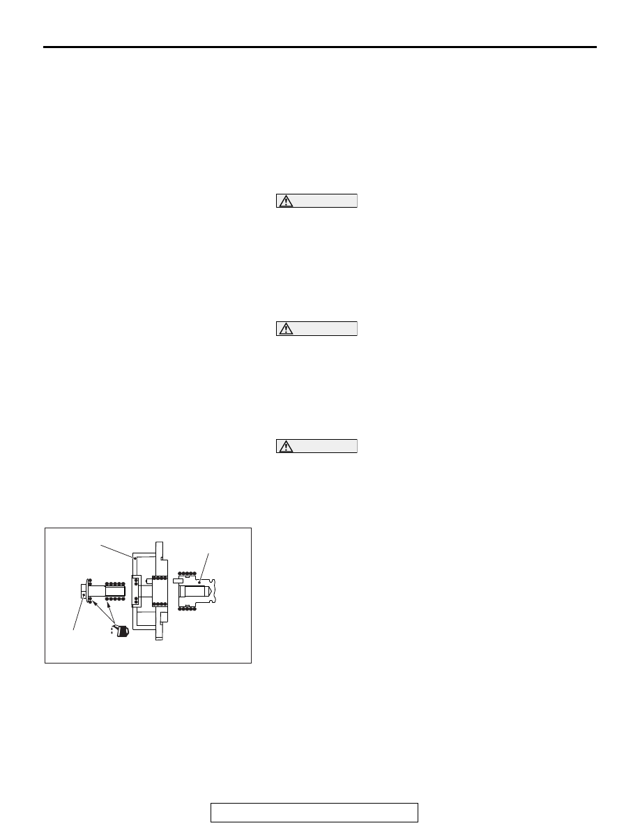
>>B<< CAMSHAFT/CAMSHAFT SPROCKET 
INSTALLATION

CAUTION

The camshaft sprocket bolt cannot be reused.
Install the camshaft and camshaft sprocket assembly as fol-
lows.
1. Check that the knock pin is set to the right overhead 

position.

2. an adequate and minimum amount of engine oil to the outer 

of the camshaft edge and the entire insertion area around 
camshaft sprocket assembly.

3. Set the knock pin hole of camshaft sprocket assembly to the 

right overhead position, and slowly insert it into the camshaft 
assembly to the specified position.

4. Install the camshaft sprocket to the camshaft.
5. Apply an adequate and minimum amount of engine oil to the 

thread of the camshaft sprocket bolt and the lower area of 
the flange.

AC708506AC

Camshaft

Camshaft 
sprocket

Camshaft 
sprocket bolt

CAMSHAFT

TSB Revision

ENGINE MECHANICAL

11A-34

6. Clamp the hexagon of the camshaft and fix it in the same 

manner as removal.

7. Tighten the camshaft sprocket bolt to the specified torque.

Tightening torque: 85 ± 5 N⋅ m (63 ± 4 ft-lb)

.

>>C<< CAMSHAFT AND CAMSHAFT SPROCKET 
ASSEMBLY (INTAKE SIDE) INSTALLATION

1. Align the intake side paint mark of the timing chain which 

was put at removal with the paint mark of the intake side 
camshaft sprocket, and install the camshaft sprocket to the 
timing chain.

2. Install the camshaft and camshaft sprocket assembly (intake 

side) to the cylinder head.

.

>>D<< THRUST CAMSHAFT BEARING 
CAP/CAMSHAFT BEARING CAP/OIL FEEDING 
CAMSHAFT BEARING CAP/CAMSHAFT 
BEARING INSTALLATION

1. Install the camshaft bearing caps to the cylinder heads.

NOTE: Because the thrust camshaft bearing cap and cam-
shaft bearing cap are the same in shape, check the bearing 
cap number and additionally its symbol to identify the intake 
and exhaust sides for correct installation.

2. Tighten each camshaft bearing cap mounting bolt to the 

specified torque in the order of number shown in the figure 
in two or three steps.

Tightening torque: 12 ± 1 N⋅ m (107 ± 8 in-lb)

.

AC611532AB

Hexagon part 
of camshaft

AC509403

AE

Paint markings
(intake side)

AC506778

AC

8

8

7

7

6

6

5

5

4

4

3

3

2

2

1

1

E  5

Engine front

Camshaft bearing cap

Camshaft bearing cap

Bearing cap No.

Identification of intake side 
and exhaust side

CAMSHAFT

TSB Revision

ENGINE MECHANICAL

11A-35

>>E<< CAMSHAFT BEARING/CAMSHAFT AND 
CAMSHAFT SPROCKET ASSEMBLY (EXHAUST 
SIDE) INSTALLATION

CAUTION

Be careful not to drop the camshaft bearing.
1. When replacing the camshaft bearing, according to the 

identification mark of front camshaft bearing cap in the table 
below, select a camshaft bearing with the corresponding 
size. Note that the identification mark of camshaft bearing is 
stamped on the place shown in the figure.

Front camshaft bearing cap

Camshaft bearing 
identification mark

Identification 
mark

Journal diameter 
mm (in)

1

40.000 - 40.008 
(1.5748 - 1.5751)

1

2

40.008 - 40.016 
(1.5751 - 1.5754)

2

3

40.016 - 40.024 
(1.5754 - 1.5757)

3

AC611697

AD

Front camshaft 
bearing cap

Identification
mark

AC708893

Notch

Identification mark

Oil hole

AD

CAMSHAFT

TSB Revision

ENGINE MECHANICAL

11A-36

2. In the same manner as removal, insert the precision 

flat-tipped screwdriver through the service hole of the timing 
chain case, press up the ratchet of timing chain tensioner to 
unlock, and hold the unlocked timing chain tensioner.
NOTE: Lightly press down the tail end of the precision 
flat-tipped screwdriver to press up the tip of the precision 
flat-tipped screwdriver inserted to the timing chain tensioner 
to unlock.

CAUTION

• When inserting special tool MB992103 into the timing 

chain case assembly, pay attention to the position of 
the timing chain to avoid damage to the timing chain 
and timing chain tension side guide. Do not insert the 
special tool MB992103 beyond its insertion guideline.

• If unlocking the timing chain tensioner is insufficient, 

the special tool MB992103 cannot be inserted to the 
insertion guideline. Do not insert the special tool 
MB992103 forcibly, follow Step 2 again to unlock the 
timing chain tensioner and insert the special tool 
MB992103.

AC509155

AC

Section A-A

A

A

Precision flat-tipped 
screwdriver

Service hole

Crankshaft pulley

Service hole

Ratchet

Precision flat-tipped screwdriver

Ratchet
release hole

Timing chain
tensioner

Ratchet

Ratchet
release hole

Timing chain tensioner
construction diagram


Content   ..  68  69  70  71   ..