Mitsubishi Lancer Evolution X. Manual - part 71


  Index      Mitsubishi     Mitsubishi Lancer Evolution X GS41EVO - service repair manual 2008 year


Search            


Content   ..  69  70  71  72   ..


Mitsubishi Lancer Evolution X. Manual - part 71


CAMSHAFT

TSB Revision

ENGINE MECHANICAL

11A-37

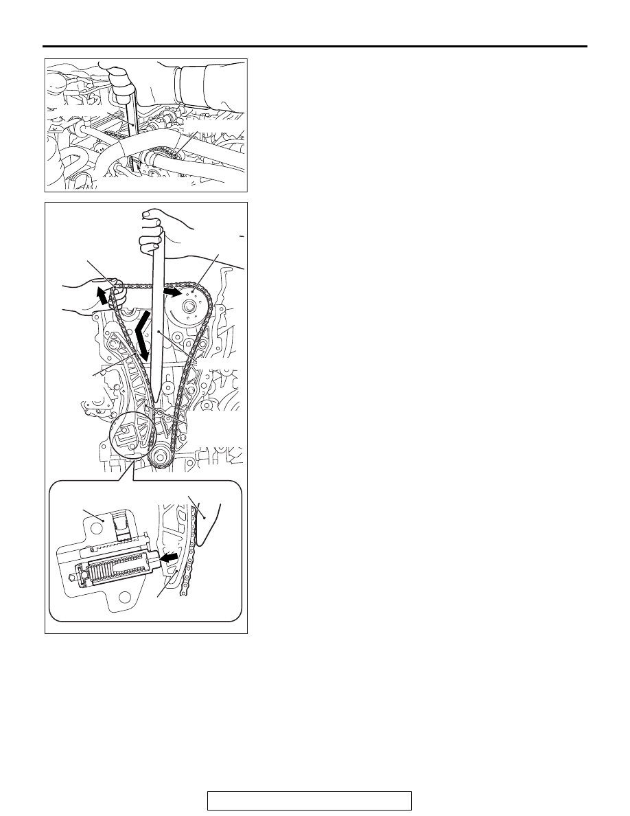
3. With the timing chain tensioner unlocked, insert special tool 

MB992103 inside the timing chain case assembly along the 
tension side of the timing chain until the insertion guide line 
aligns with the upper surface of the timing chain case 
assembly (Figure A). 
NOTE: With the timing chain tensioner unlocked, insert the 
special tool MB992103 along the tension side of the timing 
chain, according to the special tool MB992103 top shape. 
The special tool MB992103 can be inserted smoothly to the 
position where the special tool MB992103 insertion guide-
line aligns with the timing chain case assembly top surface, 
and the spread timing chain tension side guide can be hold.

4. With the special tool MB992103 inserted up to the insertion 

guide line, press the special tool MB992103 against the 
intake side camshaft sprocket (Figure B) and spread and 
hold the timing chain tension side guide (Figure C).

5. Remove the flat-tipped precision screwdriver unlocking the 

timing chain tensioner.

6. Pull up the camshaft and camshaft sprocket assembly 

(exhaust side) mounting area of the timing chain (Figure D) 
to provide allowance for easy installation of the camshaft 
and camshaft sprocket assembly (exhaust side) to the 
timing chain.

AC705456AC

Timing chain

MB992103

Insertion standard line

AC509177

AC508125

AD

MB992103

MB992103

Timing chain
tensioner

Timing chain
tension side guide

Timing chain
tension 
side guide

Timing chain
(tension side)

Camshaft
sprocket
(intake side)

Timing chain
(exhaust camshaft and
camshaft sprocket
assembly side)

A

B

C

D

CAMSHAFT

TSB Revision

ENGINE MECHANICAL

11A-38

CAUTION

When installing the camshaft and camshaft sprocket 
assembly (exhaust side), be careful not to let the camshaft 
bearing which is installed to the front cam bearing deviate 
from its position.
7. Align the exhaust side paint mark of the timing chain which 

was put at removal with the paint mark of the exhaust side 
camshaft sprocket, and install the timing chain to the 
camshaft sprocket.

8. Install the camshaft and camshaft sprocket assembly 

(exhaust side) to the cylinder head.

9. Remove the special tool inserted into the timing chain case 

assembly inside.

.

>>F<< FRONT CAMSHAFT BEARING CAP 
ASSEMBLY INSTALLATION

CAUTION

When the mounting bolts are tightened with the front cam-
shaft bearing cap tilted, the front camshaft bearing cap is 
damaged. Install the front camshaft bearing cap properly 
to the cylinder head and camshaft.
1. Install the front camshaft bearing cap to the cylinder head, 

and temporarily tighten the camshaft bearing front cap to the 
specified torque in the order of the figure (1).

Tightening torque: 17 ± 3 N⋅ m (13 ± 2 ft-lb)

2. Tighten the front camshaft bearing cap again to the specified 

torque in the order of the figure (2).

Tightening torque: 30 ± 2 N⋅ m (23 ± 1 ft-lb)

3. After installing the front camshaft bearing cap, check that the 

paint marks of camshaft sprocket and of timing chain, the 
timing mark of crankshaft pulley, and the T-mark position of 
ignition timing indicator are aligned correctly.

.

>>G<< ROCKER COVER ASSEMBLY 
INSTALLATION

1. Wipe off the sealant on the mating surface of the rocker 

cover assembly and the cylinder head and timing chain case 
assembly, and degrease the surface where the sealant is 
applied.

AC506752

AB

Paint markings
(exhaust side)

AC511062

AC

4

3

2

1

4

3

2

1

(1)

(2)

Engine front

Front 
camshaft
bearing
cap
assembly

CAMSHAFT

TSB Revision

ENGINE MECHANICAL

11A-39

CAUTION

After the installation, until a sufficient period of time (one 
hour or more) elapses, do not apply the oil or water to the 
sealant application area or start the engine.
2. Apply sealant to the joint between the cylinder head and 

timing chain case assembly as shown in the figure and 
install the rocker cover assembly to the cylinder head.

Specified sealant: Three bond 1217G or equivalent

NOTE: Install the rocker cover assembly immediately after 
the application of sealant.

3. Tighten the rocker cover assembly mounting bolts to the 

specified torque in the order of number shown in the figure.

Tightening torque: 3.0 ± 1.0 N⋅ m (27 ± 8 in-lb)

4. Tighten again the rocker cover assembly mounting bolts to 

the specified torque in the order of number shown in the 
figure.

Tightening torque: 5.5 ± 0.5 N⋅ m (49 ± 4 in-lb)

AC506753

AF

Cylinder head

Timing chain case assembly

φ 4 mm
(

φ 0.14 in)

φ 4 mm
(

φ 0.14 in)

AC506743

AE

3

6

1

9

5

10

4

8

7

11

13

14

15

16

17

18

2

12

Engine front

VALVE STEM SEAL

TSB Revision

ENGINE MECHANICAL

11A-40

VALVE STEM SEAL

REMOVAL AND INSTALLATION

M1112008100472

CAUTION

*Remove and assemble the marked parts in each cylinder unit.

Pre-removal operation
• Engine Room Under Cover Front A, B, Engine Room 

Under Cover Center and Engine Room Side Cover (RH) 

Removal (Refer to GROUP 51, Under Cover 

P.51-15

).

• Engine Oil Draining (Refer to GROUP 12, On-vehicle Ser-

vice − Engine Oil Replacemen

P.12-4

).

• Rocker Cover Assembly Removal (Refer to 

P.11A-25

).

• Engine Oil Pan Removal (Refer to 

P.11A-48

).

• Timing Chain Removal (Refer to 

P.11A-66

).

Post-installation operation
• Timing Chain Installation (Refer to 

P.11A-66

).

• Engine Oil Pan Installation (Refer to 

P.11A-48

).

• Valve Clearance Check (Refer to 

P.11A-10

).

• Rocker Cover Assembly Installation (Refer to 

P.11A-25

).

• Engine Oil Refilling (Refer to GROUP 12, On-vehicle Ser-

vice − Engine Oil Replacement 

P.12-4

).

• Engine Room Under Cover Front A, B, Engine Room 

Under Cover Center and Engine Room Side Cover (RH) 

Installation (Refer to GROUP 51, Under Cover 

P.51-15

).

AC704356

6

3

11

AC

7

12

13

1

4

5

10

9

14

N

N

2

8

15*

16*

17*

18*
19*

15*

16*

17*

18*

19*

18 ± 2 N·m
13 ± 2 ft-ib

Apply engine oil to all
moving parts before
installation.

12 ± 1 N·m
107 ± 8 in-lb  

17 ± 3 N·m
13 ± 2 ft-lb

to

30 ± 2 N·m
23 ± 1 ft-lb

12 ± 1 N·m
107 ± 8 in-lb  

Removal steps 

<<

A

>>

>>

G

<< 1.

Front camshaft bearing cap 
assembly

>>

F

<<

2.

Camshaft bearing

<<

B

>>

>>

E

<<

3.

Oil feeding camshaft bearing cap 
(exhaust side)

<<

B

>>

>>

E

<<

4.

Camshaft bearing cap (exhaust 
side)

<<

B

>>

>>

E

<<

5.

Camshaft bearing cap (exhaust 
side)

<<

B

>>

>>

E

<<

6.

Thrust camshaft bearing cap 
(exhaust side)

>>

F

<<

7.

Camshaft and camshaft sprocket 
assembly (exhaust side)

>>

F

<<

8.

Camshaft bearing

<<

B

>>

>>

E

<<

9.

Oil feeding camshaft bearing cap 
(intake side)

<<

B

>>

>>E<<

10. Camshaft bearing cap (intake side)

<<

B

>>

>>

E

<<

11. Camshaft bearing cap (intake side)

Removal steps (Continued)


Content   ..  69  70  71  72   ..