Mitsubishi Lancer Evolution 8. Manual - part 186


  Index      Mitsubishi     Mitsubishi Lancer Evolution 8 - service repair manual


Search            


Content   ..  184  185  186  187   ..


Mitsubishi Lancer Evolution 8. Manual - part 186


MANUAL TRANSMISSION  - TROUBLESHOOTING

22-7

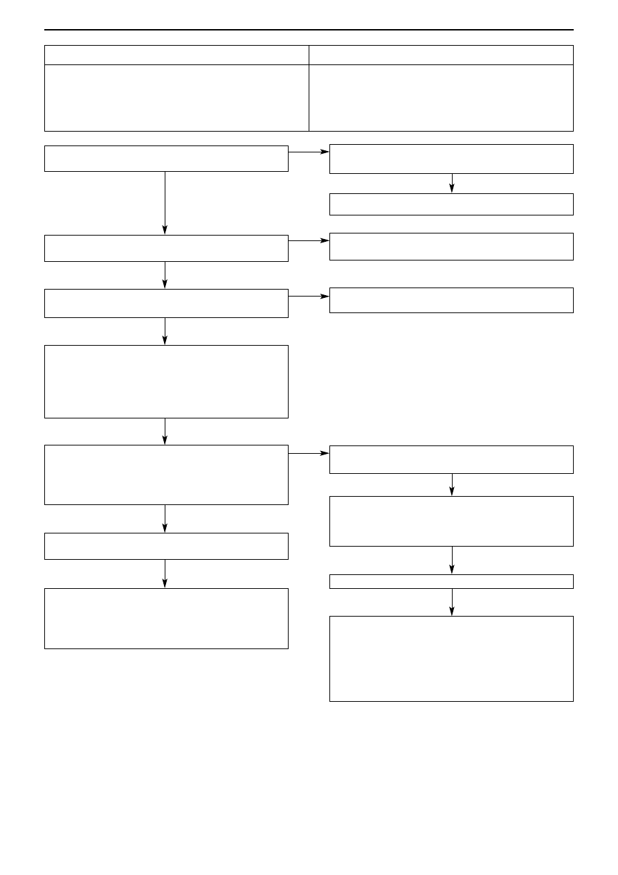
Does the reservoir tank contain the correct quantity of
fluid?

MUT-II/III Diagnosis code
• Have diagnosis code Nos.45, 46, 47 been output?

Is there a fluid leak?
YES 

add fluid

Repair leaks

Check code Nos. 45, 46, 47 pressure sensor system 
(ref. P.22-16, 17)

Check code No.81 electric pump relay system 
(ref. P.22-26)*2

Check connectors B-127, C-43, F-21
NG 

repair

Check harness between electric pump relay and body
earth
• Check earth wire to see if it is broken or damaged
NG 

repair

Replace hydraulic unit

MUT-II/III Actuator test
• No.04 Electric pump drive

OK: electric pump operating sound audible

NG 

replace 4WD-ECU

OK 

Intermittent fault 

(ref. Chapter 00 - Countermeasures for Intermittent
Malfunctions) *2

MUT-II/III Diagnosis code
• Has diagnosis code No.81 been output?

MUT-II/III Actuator test
• No.04 Electric pump drive

OK: electric pump operating sound audible

OK 

Intermittent fault

(ref. Chapter 00 - Countermeasures for Intermittent
Malfunctions) *2

B-127 Electric pump relay connector measurement
• Undo connector and take measurement on harness

side

• Voltage across 4 – earth
OK: Battery voltage

Check connector B-127
NG 

repair

Check the harness between the fusible link No.7 and
Electric pump relay
• Check power supply cable to see if it is broken, is

earthing, or is damaged

NG 

repair

Code No.82 Electric Pump Relay System

Probable causes

Code No.82 is output when the pressure sensor does not
reach the specified value, even if the 4WD-ECU has output
the electric pump motor drive command.

• Insufficient fluid
• Pressure sensor malfunction
• Hydraulic pressure unit malfunction
• Harness, connector malfunction
• 4WD-ECU malfunction
• Electric pump relay malfunction

YES

NO

NO

NG

NG

OK

NO

NO

OK

OK

YES

YES

OK

MANUAL TRANSMISSION  - TROUBLESHOOTING

22-8

5. Inspection Chart for Trouble Symptoms

6. Trouble Symptom Checking Procedures

Checking Procedure 1

C-122 Diagnosis connector measurement
• Voltage across 16 – earth

OK: Battery voltage

C-122 Diagnosis connector measurement
• Resistance across 4, 5 – body earth

OK: 2Ω or less

Replace MUT-II/III

Check connectors C-122, C-212, C-211, C-32
NG 

repair 

Confirm trouble symptoms

Check harness between fusible link No.1 and diagnosis
connector
• Check to see if power supply cable is broken or

damaged

NG 

repair

Check connector C-122

Confirm trouble symptoms

Check harness between body earth and diagnosis
connector
• Check earth wire to see if it is broken or damaged
NG 

repair

Fault symptom

Checking Procedure No. Page

No communication possible between MUT-II/III and any other system

1

22-8

No communication possible between MUT-II/III and any other system

Possible causes

It is possible that there is a malfunction in the diagnosis connector
power supply circuit, the earth circuit, or the MUT-II/III.

• Diagnosis connector malfunction
• Harness, connector malfunction
• MUT-II/III malfunction

OK

OK

NG

NG

NG

NG

OK

OK

MANUAL TRANSMISSION  - ON-VEHICLE SERVICING

22-9

On-vehicle Servicing

1. Changing transmission oil <6 M/T>

Servicing information other than that noted below remains the same.

Transmission oil
Specified transmission oil:
Mitsubishi DIA QUEEN SUPER MULTIGRADE OIL <75W/85W>
Quantity: 2.2 dm

3

2. Select cable (inside cabin) adjustment <6M/T>

1.  Put gear stick in the neutral position
2.  Remove front floor console. (ref. ’01-1 Lancer Evolution  VII Service

Manual (No.1036K02) – Chapter 52A)

3.  Disconnect the select cable from the select lever
4.  Move the gear stick towards the 5th and 6th gears so that it touches the

stopper, then check the cable connection is secure and the assembly is
running smoothly (run-in).

5. Remove hand from gear stick, and allow it to return naturally to the

neutral position

6.  Move the select cable lock clip in the direction of the arrow in the

diagram, pulling the fastening clip

7.  Without moving the gear stick from the neutral position, connect the

select cable to the select lever.

8.  Adjust the select cable

9.  Press the select cable fastening clip in, and move the lock clip back.
10. Check by shifting the gear stick into each gear.

NOTE
Repeat steps 3and10 if the gear stick does not go into a gear, or if it
catches and does not move smoothly.

11. Fit the front floor console

(ref.  ’01-1 Lancer Evolution VII Service Manual  (No. 1036K02) –
Chapter 52A)

Filler plug

Drain plug

5

th

, 6

th

gear side

Select lever

Middle
position

Select cable

Lock clip

Fastening clip

Fastening clip

Lock
clip

MANUAL TRANSMISSION  - TRANSMISSION CONTROL<6M/T>

22-10

Transmission Control <6M/T>

Removal and Fitting

CAUTION
1. On the gear stick ASSY, do not disassemble anything other than the distance piece and bush. (Non-supplied

parts)

2.  Never use mineral oil on the moving parts of the gear stick ASSY. This is because if mineral oil is used, it could

cause plastic parts to break.

Pre-removal and post-fitting operations
• Removal and fitting of air cleaner ASSY
• Removal and fitting of air by-pass hose, air hose E, air

pipe C, air hose D (ref. Chapter 15 – Intercooler)

• Removal and fitting of battery, battery tray

Caution: SRS
Do not subject the SRS-ECU to any shocks when
removing or fitting shift and select cable ASSY, or gear
stick ASSY.

Shift cable & select cable ASSY removal
procedure
1. Gear stick knob
•  Front floor console
2. Front floor console bracket
3. Select cable connection (inside cabin)
4. Shift cable connection (inside cabin)
5. Clip (inside cabin)
6. Snap pin
7. Shift cable connection (transmission side)
8. Select cable connection (transmission
side)
9. Clip (transmission side)
10. Shift cable & select cable ASSY

Gear stick ASSY fitting procedure
1. Gear stick knob
•  Front floor console
2. Front floor console bracket
3. Select cable connection (inside cabin)
4. Shift cable connection (inside cabin)
5. Clip (inside cabin)
11. Gear stick ASSY
12. Distance piece
13. Bush


B


A


A


A


B


A


B


Content   ..  184  185  186  187   ..