Mitsubishi Lancer Evolution 8. Manual - part 185
Tools
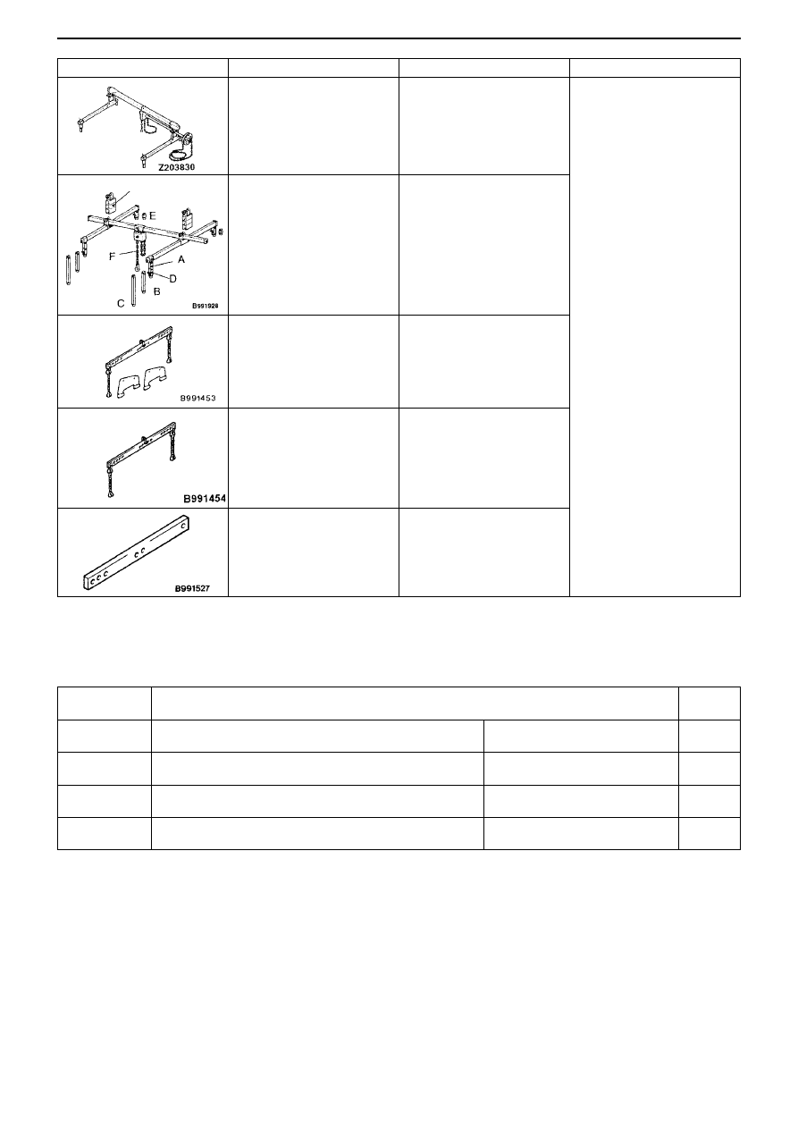
Number
Name
Use
Recommended tools
Anzen Jidosha (Co. Ltd)
MZ203831
Or
Banzai (Co. Ltd)
MZ203830
MB991928
A: MB991929
B: MB991930
C: MB991931
D: MB991932
E: MB991933
F: MB991934
MB991453
MB991454
MB991527
Engine lifter
Engine lifter
A: Joint (50) x 2
B: Joint (90) x 2
C: Joint (140) x 2
D: Feet (stand) x 4
E: Feet (short) x 2
F: Chain & hook ASSY
Engine lifter attachment set
Engine lifter balancer
Engine lifter
To hold the engine ASSY
when removing or fitting the
transmission.
Note
1. The engine lifter balancer
(MB991454) is one part of
the engine lifter ASSY
(MB991453).
2. Only use a chain with the
engine lifter balancer
(MB991454)
MANUAL TRANSMISSION – SPECIAL TOOLS, TROUBLESHOOTING 22-3
Troubleshooting
1. Diagnosis Code List
Slide bracket (HI)
Diagnosis code
No.
Diagnosis item
Reference
page
31
Steering sensor <ST-1, ST-2, ST-N> system
Broken wire or short
22-4
63
Parking brake switch system
Short or forgotten to return
22-5
65
ABS monitor system (vehicles fitted with ACD + AYC)
Broken wire or ABS fault
22-6
82
Electromotive pump relay system
Electromotive pump fault or
pressure sensor abnormality
22-7