Mitsubishi Lancer Evolution 8. Manual - part 8


  Index      Mitsubishi     Mitsubishi Lancer Evolution 8 - service repair manual


Search            


Content   ..  6  7  8  9   ..


Mitsubishi Lancer Evolution 8. Manual - part 8


POWER TRAIN – MANUAL TRANSMISSION

2-11

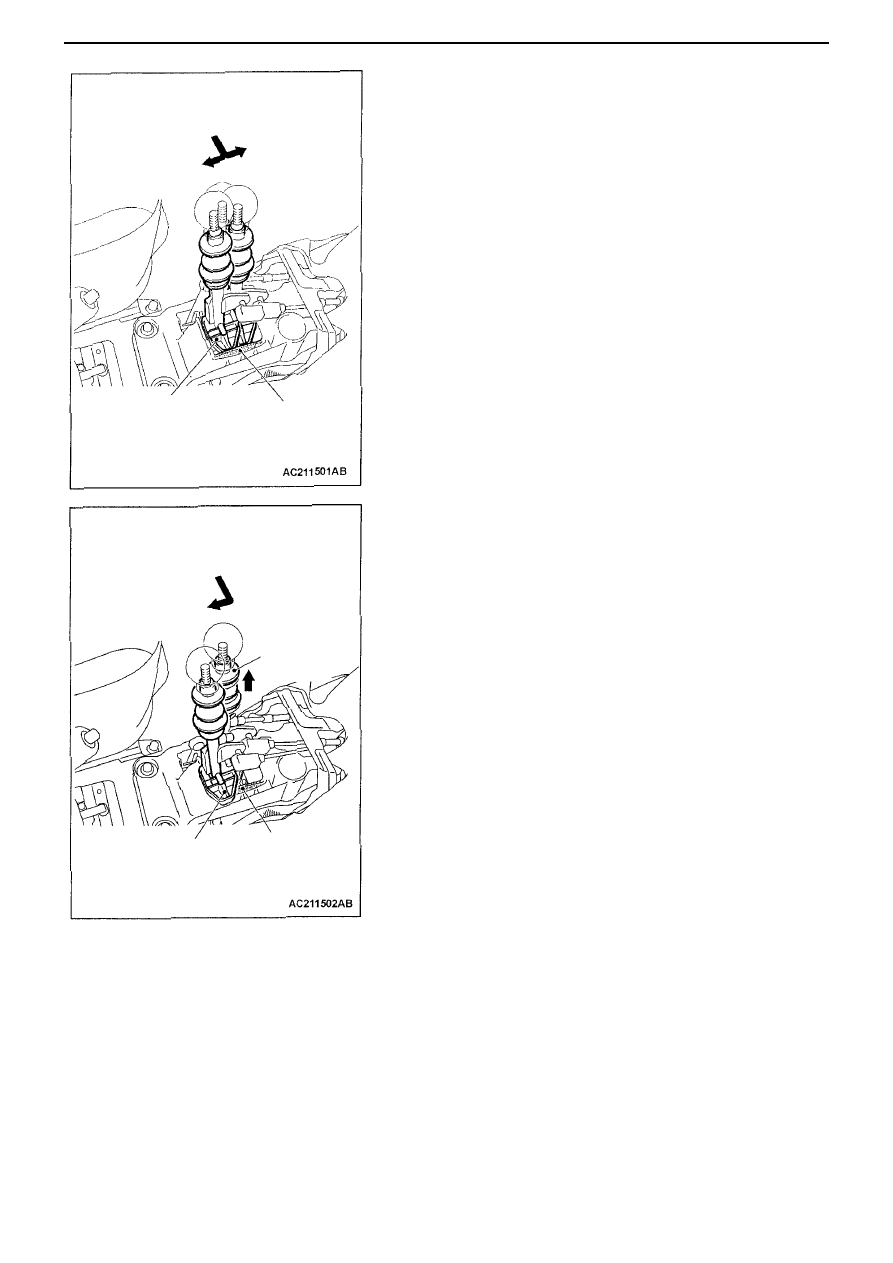
Reverse Gear protection when changing into 5

th

or 6

th

gear

The lock moves against the base bracket when shifting to 5

th

or 6

th

gear,

thus preventing a change into reverse.

When engaging reverse

Reverse can be engaged by pulling up the collar beneath the gear knob

Engaging to
5

th

gear

Engaging to
6

th

gear

Lock

Base bracket

Engaging reverse

Lift the collar

Lock

Base bracket

POWER TRAIN – ACD AND AYC

2-12

Active Centre Differential (ACD) and Active Yaw Control (AYC)

General information

The following has been changed with the new additions to the Lancer Evolution-VIII.
• Super AYC has been adopted in the rear differential (refer to P. 2-14).
• Only one position in line with the adoption of Super AYC.

Electronic control system

4WD-ECU

The 4WD-ECU ABS monitor terminal No. 49 has changed to No. 48 in line with the adoption of Super AYC.
Other terminal numbers are the same as for the Lancer Evolution-VII. However, if the 4WD-ECU for the Lancer Evolution-VII is
mounted in the Lancer Evolution-VIII, it becomes AYC control defect, and Diagnosis Code No. 65 appears 60 seconds after
Ignition is switched ON and the ACD and AYC systems stop. (the same applies if the 4WD-ECU for the Lancer Evolution-VIII is
mounted in the Lancer Evolution-VII)

POWER TRAIN – PROPELLER SHAFT, FRONT AXLE AND REAR AXLE 2-13

Propeller Shaft

The specifications of the propeller shaft have changed as follows for the 6M/T mounting.

Specifications
Item

New 6M/T

New and old 5M/T

Universal joint

Journal diameter mm

18.3

16.3

Front Axle

EBJ has been adopted in the drive shaft wheel constant velocity joints.

Specifications
Item

New

Old

Wheel

EBJ

*1

BJ

Joint type

Transmission

TJ


LH

352.5 x 26

350 x 26

Drive shaft

Shaft length

*2

 x Shaft

diameter mm

RH

429.5 x 26

427 x 26

Notes
*1: EBJ: by adopting 8 reduced diameter balls, the velocity joints weigh less and are more compact than
      the original BJ
*2: The location of the central point of each joint is shown.

Rear axle

EBJ has been adopted in the drive shaft wheel constant velocity joints.

Specifications

New

Old

Item

AYC not
mounted

AYC
mounted

AYC not
mounted

AYC
mounted

Wheel

EBJ

*1


BJ


Joint type

Trans-
mission

TJ


TJ


LH

485.6 x 25

428.5 x 25

483 x 25

426 x 25

Drive
shaft

Shaft length

*2

 x

Shaft diameter
mm

RH

575.5 x 25

448.5 x 25

573 x 25

446 x 25

Notes
*1: EBJ: by adopting 8 reduced diameter balls, the velocity joints weigh less and are more compact than
the original BJ
*2: The location of the central point of each joint is shown.

Propeller Shaft

Front Axle

Rear Axle

the original BJ

POWER TRAIN – DIFFERENTIAL

2-14

Differential

The differential has changed as follows.
• Optimisation and weight saving of the differential carrier wall thickness (RS)
• Installation of super AYC (standard for GSR; optional for RS)

Super AYC

The performance in track competitions such as rally cross and circuit races has improved significantly with AYC, where the
torque differential has increased by 1.6 compared to the original by changing the design of the AYC torque transfer differential.
It is has the following features.
• Turning characteristics: The yaw has increased because of the increased torque differential between the right and left

wheels. The turn-in has improved further and understeer is reduced.

• Traction performance: Improved performance (LSD effect) on a wide range of road conditions
• The original case-to-shaft system (system of transmitting torque between the differential case and the right axle) has been

changed to a shaft-to-shaft system in order to increase the amount of torque movement.

• The differential mechanism has changed from bevel gear to a planetary gear type in order to operate the shaft-to-shaft

system.

Construction Diagram
New: Super AYC (shaft-to-shaft system) 

Old: AYC (case-to-shaft system)

Differential
mechanism
planetary
gear system

Input axle

Fluctuating speed gear

Set of 2 clutches

Differential
mechanism
bevel gear
system

Fluctuating
speed gear

Input axle

Left
axle

Right
axle

Left
axle

Right
axle


Content   ..  6  7  8  9   ..