Mitsubishi Lancer Evolution 8. Manual - part 6
POWER TRAIN – MANUAL TRANSMISSION
2-3
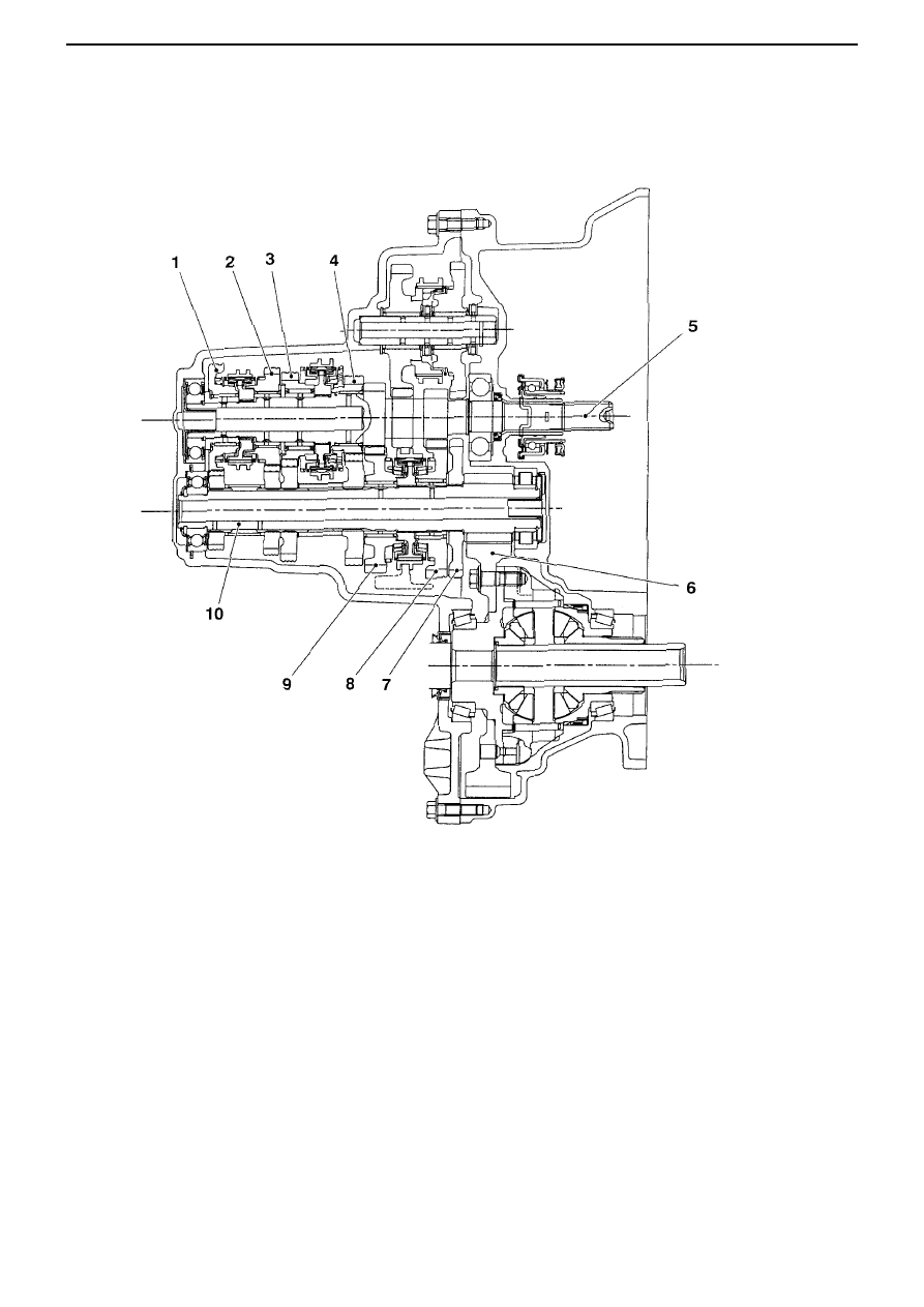
Sectional view
W6MAA (6-speed manual transmission)
1. 6
th
gear
2. 5
th
gear
3. 4
th
gear
4. 3
rd
gear
5. Input shaft
6. Final gear
7. Reverse gear
8. 1
st
gear
9. 2
nd
gear
10. Output shaft (main shaft)
AC211869AB