Mitsubishi Lancer Evolution 8. Manual - part 4


  Index      Mitsubishi     Mitsubishi Lancer Evolution 8 - service repair manual


Search            


Content   ..  1  2  3  4  5  ..


Mitsubishi Lancer Evolution 8. Manual - part 4


ENGINE (4G6) – CONTROL SYSTEM

1-9

Control System

The following changes have been made to the controls of the 4G63-DOHC-Turbocharger engine installed in the original
Lancer Evolution-VII:
• MDP (Manifold Differential Pressure) sensor has been discontinued.
• EGR control has been discontinued.
• Diagnostic control terminal has been discontinued.

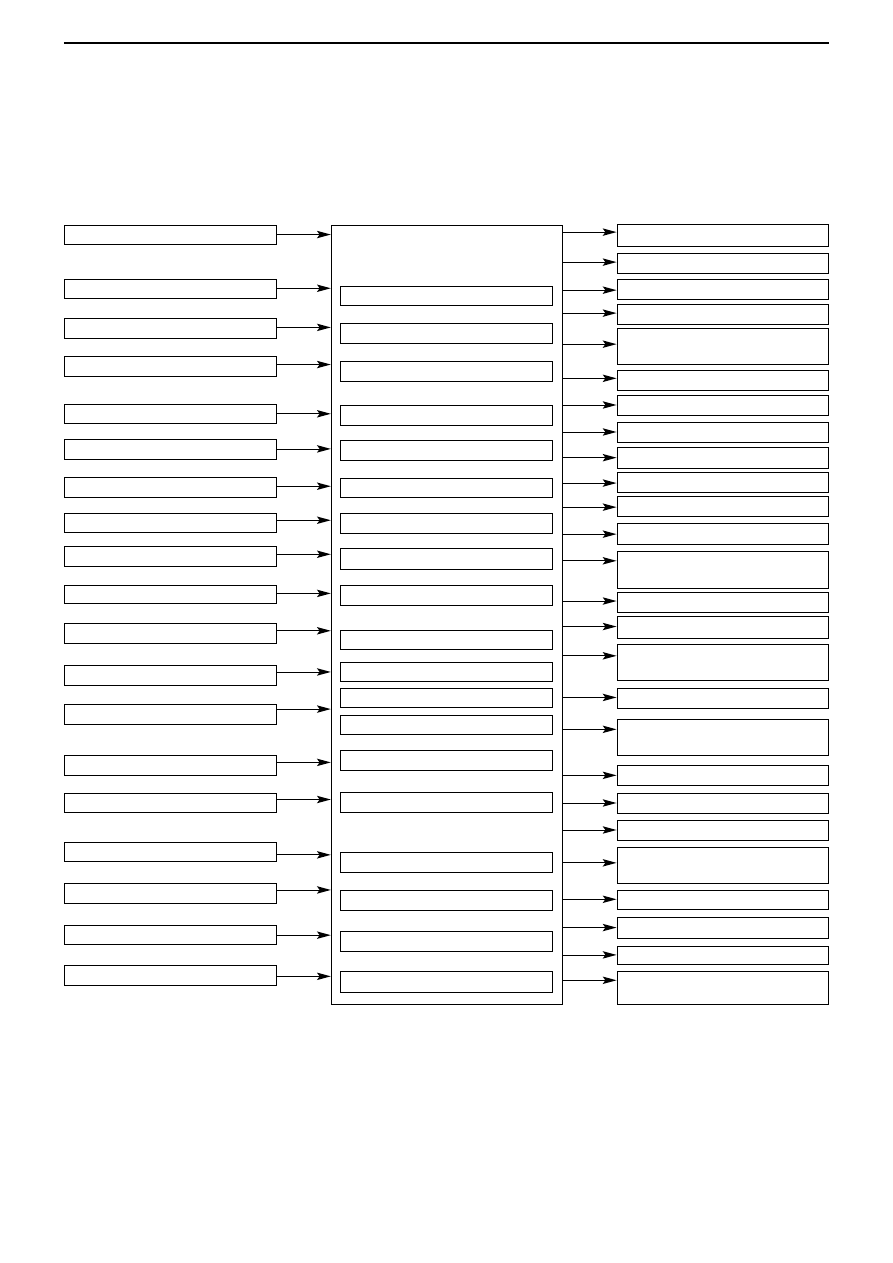
System block diagram

Air flow sensor

Intake air temperature sensor

Barometric pressure sensor

Engine coolant temperature sensor

Throttle position sensor

A/C switch

A/C load signal

Camshaft position sensor

Crank angle sensor

Alternator FR sensor

Vehicle speed sensor

Power steering fluid pressure switch

Detonation sensor

Intercooler water spray (auto)

Intercooler water spray (manual)

Oxygen sensor

Ignition switch-IG

Ignition switch-ST

Power supply

Fuel injection control

Idle speed control

Ignition timing control

Engine control relay control

Fuel pump relay control

A/C relay control

Fan motor control (radiator)

Fan relay control (A/C condenser)

Alternator control

Air flow sensor filter reset control

Fuel pressure control

Turbocharger

Secondary air control

Intercooler water spray control

Engine warning light control

Oxygen sensor heater control

Purge control

Diagnosis output

RAM data transmission

No.1 injector

No.2 injector

No.3 injector

No.4 injector

Idle speed control servo (stepper
motor)

No.1, No. 4 ignition coil

No.2, No.3 ignition coil

Engine control

Fuel pump relay 2

Fuel pump relay 3

A/C relay

Fan controller (radiator)

Fan motor relay (HI, LOW) (A/C
condenser)

Alternator G terminal

Air flow sensor

Fuel pressure control solenoid
valve

Waste gate solenoid valve

Secondary air control solenoid
valve

Intercooler water spray relay

Intercooler water spray light

Tachometer

Engine warning light (check
engine light)

Oxygen sensor heater

Purge control solenoid valve

Engine ECU

Diagnosis output terminal

Diagnosis output terminal (for
MUT - II)

ENGINE (4G6) – CONTROL SYSTEM

1-10

1 Injector

2 Idle speed control

servo

3 Fuel pressure control

solenoid valve

4 Waste gate solenoid

valve

5 Purge control solenoid

valve

6 Secondary air control

solenoid valve

• Engine control relay
• Fuel pump relay 2, 3
• A/C relay
• Ignition control
• Fan controller
• Condenser fan relay (HI)
• Condenser fan relay

(LOW)

• Engine warning light
• Diagnosis output
• Alternator G terminal
• Intercooler water spray

relay

• Intercooler water spray

light

Control system diagram

1 Oxygen sensor

2 Air flow sensor

3 Intake air temperature

sensor

4 Throttle position

Sensor

5 Camshaft position

sensor

6 Crank angle sensor

7 Barometric pressure

sensor

8 Engine coolant

temperature sensor

9 Detonation sensor

• Power supply
• Ignition switch-IG
• Ignition switch-ST
• Vehicle speed sensor
• A/C switch
• A/C load signal
• Power steering fluid

pressure switch

• Alternator FR terminal
• Intercooler water spray

switch (Auto)

• Intercooler water spray

switch (Manual)

6 Secondary air

control solenoid valve

5 Purge control solenoid valve

Canister

Check
valve

By-pass valve

4 Throttle

position Sensor

2 Idle

speed control
servo

Vacuum
tank

3 Fuel pressure control

solenoid valve

Secondary air valve

Air
inlet

2 Air flow sensor

7 Barometric pressure sensor

3 Intake

air temp.
sensor

1

Oxygen
sensor

Fuel pressure
regulator

4 Waste gate

solenoid valve

Waste gate
actuator

1 Injector

Catalytic converter

Engine

-ECU

From fuel
tank

To
fuel
tank

From
fuel
pump

5 Camshaft position sensor

8 Engine coolant temperature

sensor

9 Detonation sensor

6 Crank angle sensor

ENGINE (4G6) – CONTROL SYSTEM

1-11

1. Fuel injection control

This is basically the same as the control system in the 4G63-DOHC-Turbocharger engine installed in the original Lancer
Evolution-VII.

System configuration diagram

Fuel pressure control
solenoid valve

To fuel tank

Injector

Engine

ECU

Air flow sensor

Intake air temp. sensor

Barometric pressure sensor

Throttle position sensor

Ignition switch-ST

Oxygen sensor

Vehicle speed sensor

Crank angle sensor

Detonation sensor

Engine coolant temp. sensor

Camshaft position sensor

Bimetal type limiter

To intake manifold

From air cleaner

Speed adjusting screw

Air flow sensor

Barometric pressure sensor

Air intake temp. sensor

Engine coolant temp. sensor

Throttle position sensor

Crank angle sensor

A/C switch

A/C load signal

Vehicle speed sensor

Power steering fluid pressure switch

Alternator FR terminal

Ignition switch-IG

Ignition switch-ST

Diagnosis control terminal

Engine

ECU

Idle speed
control servo
(Stepper motor)

2. Idle speed control

This is basically the same as the control system in the 4G63-DOHC-Turbocharger engine installed in the original Lancer
Evolution-VII.

System configuration diagram

6FU2823

X6046AU

Fuel pressure
regulator

From
fuel
pump

ENGINE (4G6) – CONTROL SYSTEM

1-12

3. Ignition timing and distribution control

Basically the same control system has been adopted as in the 4G63-DOHC-Turbocharger engine installed in the original
Lancer Evolution-VII.

System configuration diagram

4. Other controls

The following controls are basically the same as the control systems adopted in the 4G63-DOHC-Turbocharger engine
installed in the original Lancer Evolution-VII.
• Radio fan motor relay control
• Power supply
• Air flow sensor filter reset control
• Fuel pressure control
• Supercharging pressure control
• Secondary air control
• Fuel pump control
• A/C condenser fan relay control
• Alternator control
• Oxygen sensor heater control
• Purge control

Please refer to Emission Control System.

5. Diagnosis system

The engine ECU has the following functions in order to facilitate system checks.
a. Engine warning light
b. Diagnosis function
c. Service data output
d. Actuator test

Note
Please refer to the maintenance manual for each item.

Engine

ECU

Ignition coil B

Air flow sensor

Barometric pressure sensor

Air intake temp. sensor

Engine coolant temp. sensor

MDP sensor

Crank angle sensor

Camshaft position sensor

Vehicle speed sensor

Ignition switch-ST

Detonator sensor

Ignition coil A

Ignition
switch

Battery

Spark plug

Cylinder No.

X6047AU


Content   ..  1  2  3  4  5  ..