Mitsubishi Lancer Evolution 8 MR. Manual - part 4
ENGINE (4G6) – GENERAL, BASE ENGINE (6 M/T)
1-9
★
1. O2 sensor
★
2. Air flow sensor
★
3. Air intake sensor
★
4. Throttle position
sensor
★
5. Cam position sensor
★
6. Crack angle sensor
★
7. Atmospheric pressure
sensor
★
8. Water temperature
sensor
★
9. Knock sensor
• Power supply
• Ignition switch IG
• Ignition switch ST
• Vehicle speed sensor
• A/C switch
• A/C load signal
• Power steering fluid
pressure switch
• Alternator FR signal
• Intercooler water spray
switch (auto)
• Intercooler water spray
switch (manual)
✩
1. Injector
✩
2. ISC servo (stepper
motor)
✩
3. Fuel pressure control
solenoid valve
✩
4. No.1 wastegate solenoid
valve
✩
5. No.2 wastegate solenoid
valve
✩
6. Purge control solenoid
valve
✩
7. Secondary air control
solenoid valve
• Engine control relay
• Fuel pump relay 2, 3
• A/C relay
• Ignition coil
• Fan controller
• Condenser fan relay (HI)
• Condenser fan relay
(LOW)
• Engine warning lamp
• Diagnosis output
• Alternator G terminal
• Intercooler water spray
relay
• Intercooler water spray
lamp
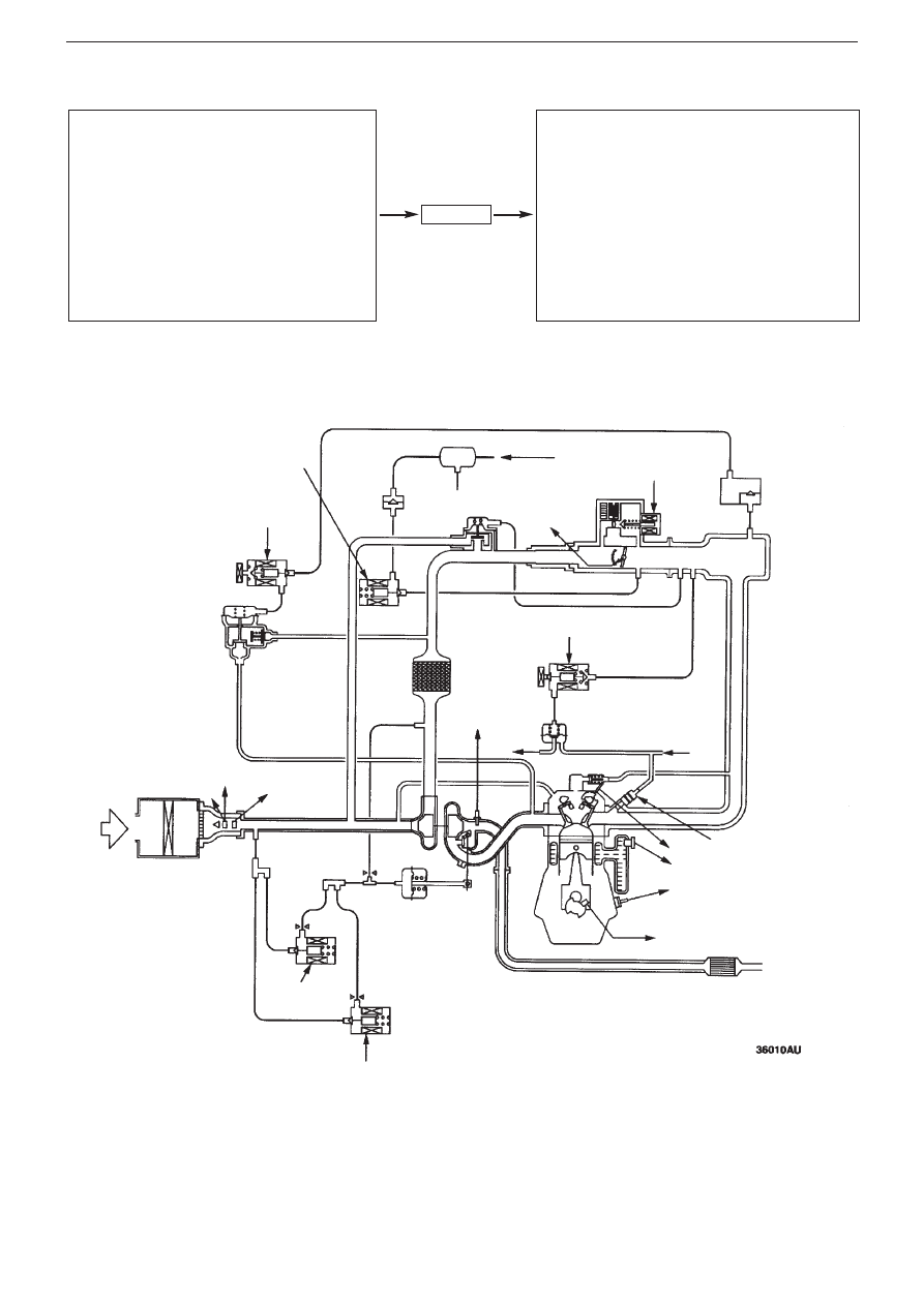
Engine ECU
✩
6. Purge control
solenoid valve
Canister
✩
7. Secondary air
control solenoid valve
From fuel tank
Secondary
air valve
By-pass
valve
★
1. O
2
sensor
✩
3. Fuel pressure
control solenoid valve
★
4. Throttle
position
sensor
★
7. Atmospheric pressure
sensor
★
3. Air intake
sensor
★
2. Air flow sensor
✩
4. No.1
wastegate
solenoid valve
✩
5. No.2 wastegate
solenoid valve
Only operates on 6M/T
Wastegate actuator
Fuel pressure
regulator
✩
1. Injector
★
5.Cam position sensor
★
8.Water temperature sensor
★
9.Knock sensor
Crack angle sensor
Catalytic converter
Air
intake
Check
valve
✩
2. ISC servo
Vacuum
tank
From fuel
pump
To fuel
tank
Control system diagram