Mitsubishi Lancer Evolution 8 MR. Manual - part 3
ENGINE (4G6) – BASE ENGINE (6 M/T)
1-5
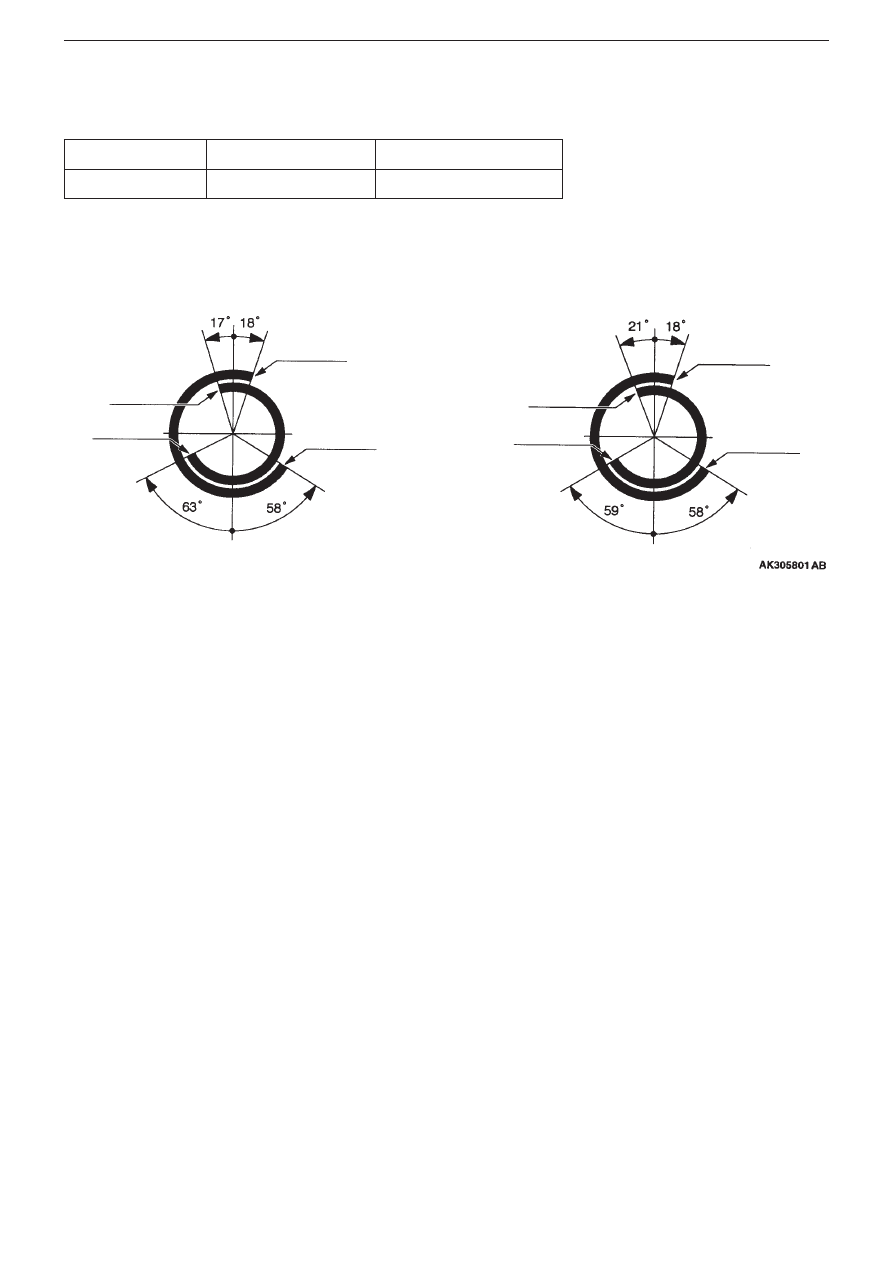
6. Camshaft
Output at high engine speeds has been improved by altering the cam profile of the intake camshaft, and optimizing the valve
timing.
Evolution VIII MR
Evolution VIII
Cam height mm
35.96
35.79
Evolution VIII MR
Evolution VIII
T.D.C (top dead centre)
T.D.C (top dead centre)
Intake valve open
Intake valve
closed
Exhaust
valve closed
Exhaust
valve open
Intake valve open
Intake valve
closed
Exhaust
valve closed
Exhaust
valve open
B.D.C (Bottom dead centre)
B.D.C (Bottom dead centre)