Mitsubishi Lancer Evolution 7. Manual - part 387
CHASSIS ELECTRICAL
-
Hazard Warning Lamp Switch/Horn/Cigarette Lighter
ILL
ILL
54A-37
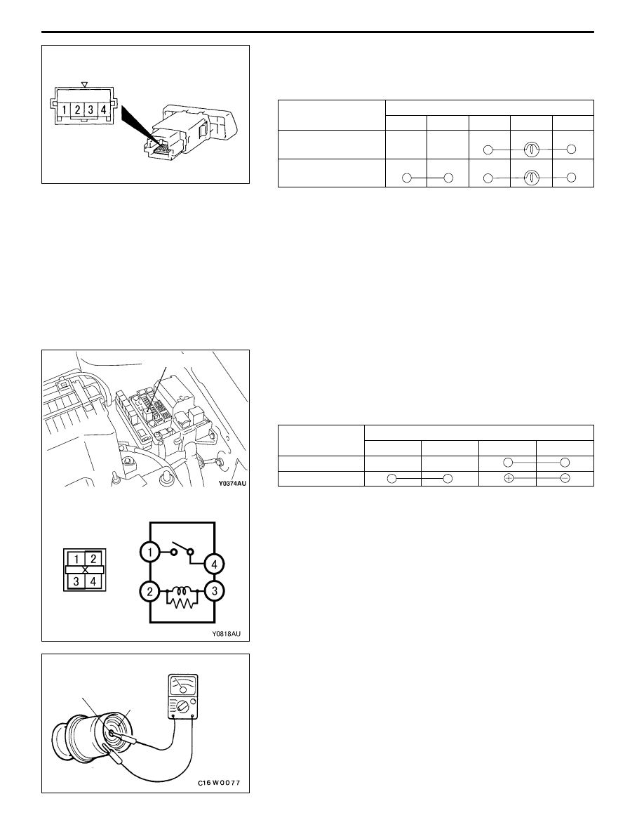
INSPECTION
HAZARD WARNING LAMP SWITCH CONTINUITY
CHECK
Switch Position
Terminal No.
1
2
3
4
OFF
ON
HORN
INSPECTION
HORN RELAY CONTINUITY CHECK
Switch Position
Terminal No.
1
4
3
2
De-energized
Energized
CIGARETTE LIGHTER
INSPECTION
D
Remove plug and check for wear on spot.
D
Check for residual cigarette or foreign object on element.
D
With circuit tester, check for element continuity.
<Except Japan-spec. models>
Horn relay
Spot
Element