Mitsubishi Lancer Evolution 7. Manual - part 385


  Index      Mitsubishi     Mitsubishi Lancer Evolution 7 - service repair manual


Search            


Content   ..  383  384  385  386   ..


Mitsubishi Lancer Evolution 7. Manual - part 385


CHASSIS ELECTRICAL -

Headlamp Assembly

CHASSIS ELECTRICAL -

Headlamp Assembly

CHASSIS ELECTRICAL -

Headlamp Assembly

54A-29

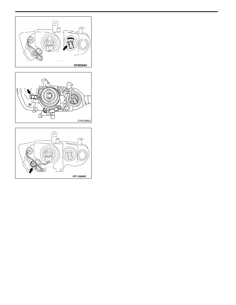
HEADLAMP BULB (HIGH BEAM)REPLACEMENT

(1) Disconnect battery.

(2) Disconnect connector.

(3) Screw out socket to pull out bulb.

(4) After bulb is replaced, properly reconnect connector.
Caution

Do not touch bulb surface bare-handed or with dirty

gloves. If dirt is attached on glass surface of the bulb,

immediately use alcohol or thinner to remove dirt, and

install the bulb after well dried.

POSITION LAMP BULB REPLACEMENT

1. Remove the splash shield.
2. Disconnect the connector and remove the socket of the

position lamp by turning to left.

Caution

Do not touch bulb surface bare-handed or with dirty

gloves. If dirt is attached on glass surface of the bulb,

immediately use alcohol or thinner to remove dirt, and

install the bulb after well dried.

FRONT TURN-SIGNAL LAMP BULB

REPLACEMENT

1. Remove the splash shield.
2. Disconnect the connector and remove the socket of the

front turn signal lamp by turning to left.

Caution

Do not touch bulb surface bare-handed or with dirty

gloves. If dirt is attached on glass surface of the bulb,

immediately use alcohol or thinner to remove dirt, and

install the bulb after well dried.

HEADLAMP AUTO CUT ADJUSTMENT

PROCEDURE

Headlamps are controlled smart wiring system (SWS). For

adjustment procedure of headlamp auto lamp and headlamp

auto cut, refer to GROUP 54B.

HEADLAMP AUTO CUT FUNCTION CHECK

When lighting switch is turned ON (to HEAD position) with

ignition switch removed from ignition key cylinder and driver’s

door is opened, ensure that headlamps are switched off after

one second. When headlamps are inoperative, perform

troubleshooting. (Refer to GROUP 54B.)

Headlamp bulb

<High beam>

Position lamp

CHASSIS ELECTRICAL -

Headlamp Assembly

CHASSIS ELECTRICAL -

Headlamp Assembly

54A-30

HEADLAMP ASSEMBLY

REMOVAL AND INSTALLATION

2

3

1

AY2103AU

1. Headlamp leveling switch

Headlamp removal steps
D

Front bumper (Refer to GROUP 51)

2. Air guide panel
3. Headlamp assembly

INSPECTION

HEADLAMP LEVELING SWITCH CONTINUITY CHECK

Switch Position

Resistance between the termi-

nal 4 and 5 (Ω)

0

120

1

300

2

620

3

1.1 k

4

2 k

CHASSIS ELECTRICAL -

Side Turn-signal Lamp/Room Lamp

54A-31

SIDE TURN-SIGNAL LAMP

SPECIAL TOOL

Tools

Number

Name

Use

MB990784

Ornament remover

Side turn-signal lamp removal

SIDE TURN-SIGNAL LAMP

REMOVAL SERVICE POINT

Use special tool, etc. to press and deflect hook to vehicle

front from fender, and unhook the pawls to remove side

turn-signal lamp.

INSTALLATION SERVICE POINT

Insert pawls into fender panel and install side turn-signal lamp.

ROOM LAMP

TROUBLESHOOTING

For troubleshooting of room lamp, refer to GROUP 54B.

Side turn-signal lamp

MB990784

Front of vehicle

AX0386CA

Fender pane

Hook

Tab

Fender panel

Front of vehicle

CHASSIS ELECTRICAL

-

Rear Combination Lamp

54A-32

REAR COMBINATION LAMP

SPECIAL TOOL

Tool

Number

Name

Use

MB990784

Ornament remover

Rear combination lamp removal

TROUBLESHOOTING

For troubleshooting on rear combination lamps, refer to GROUP 54B.

REAR COMBINATION LAMP

REMOVAL AND INSTALLATION

4

2

1

5

3

1. Rear fog lamp switch

Removal steps

2. Rear combination lamp assembly

3. Rear combination lamp body

4. Socket assembly

5. Bulb


Content   ..  383  384  385  386   ..