Mitsubishi Lancer Evolution 7. Manual - part 383


  Index      Mitsubishi     Mitsubishi Lancer Evolution 7 - service repair manual


Search            


Content   ..  381  382  383  384   ..


Mitsubishi Lancer Evolution 7. Manual - part 383


CHASSIS ELECTRICAL -

Combination Meter

54A-21

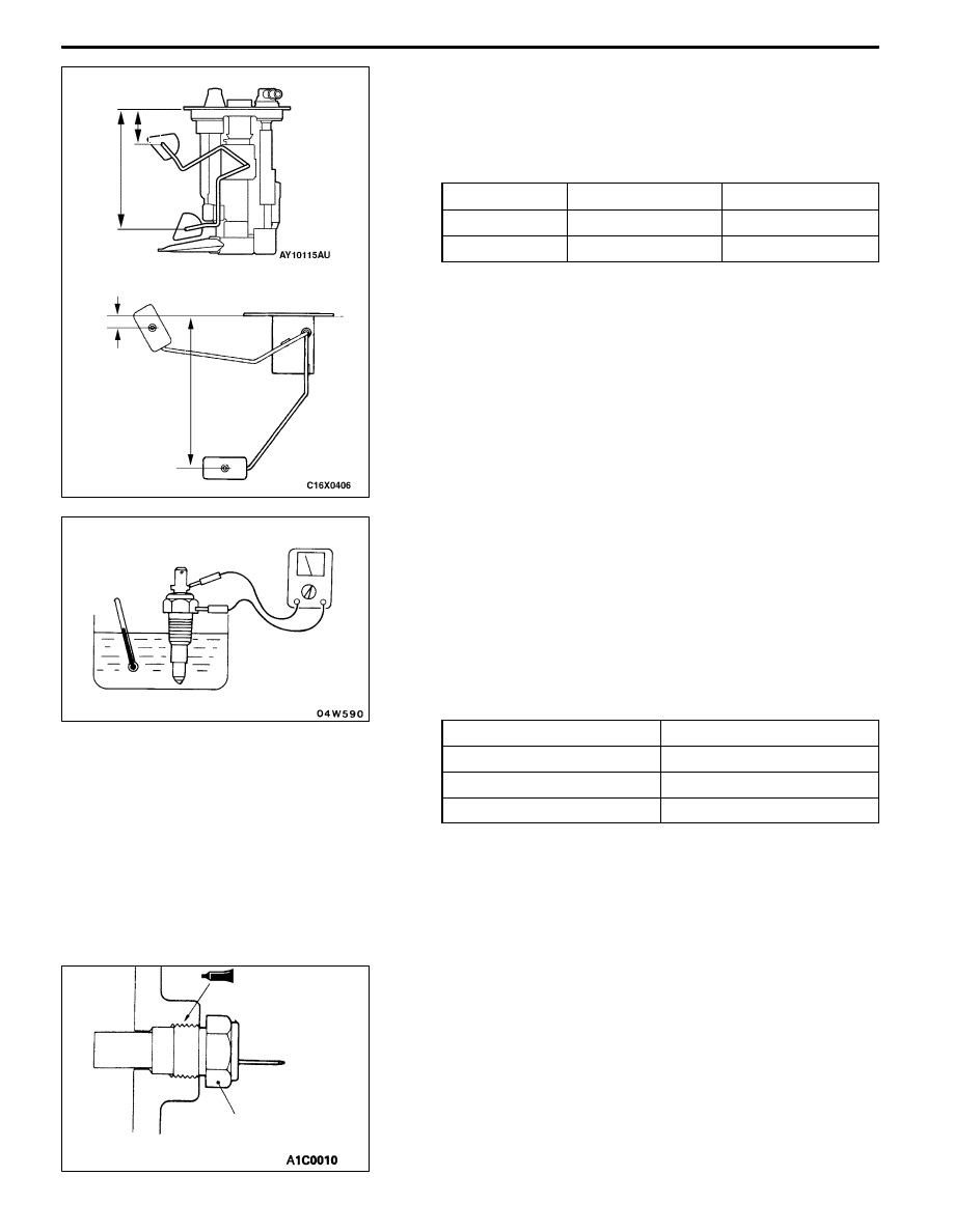
FLOAT HEIGHT OF FUEL GAUGE UNIT
When float is moved to contact float arm on stopper,

ensure that Position F (A) and E (B) are within standard

value.

Standard Value:

Float Position

Main fuel gauge unit

Sub fuel gauge unit

Float Position

Main fuel gauge unit

Sub fuel gauge unit

Position F (A)

33.3 mm

10.7 mm

Position E (B)

121.9 mm

138.6 mm

ENGINE COOLANT TEMPERATURE GAUGE

UNIT CHECK

1. Drain coolant. (Refer to GROUP 14 - On-vehicle Service)

2. Remove water temperature gauge unit.

3. Put water temperature gauge unit into the hot water in

specified temperature, and ensure that basic resistance

is within standard value.
Standard value: 70_C 104 ± 13.5 
Reference value:

Temperature

Resistance Ω

50_C

230

60_C

155

80_C

73

4. After inspection, apply specified sealant at threads of

water temperature gauge unit, and tighten to the specified

torque.
Semi-drying sealant: 3M ATD Part No.1215 or

equivalent

5. Refill coolant. (Refer to GROUP 14 - On-vehicle Service.)

Main fuel gauge unit

Sub fuel gauge unit

A

B

A

B

Thermometer

Circuit tester

11

±

1 N·m

CHASSIS ELECTRICAL -

Combination Meter

54A-22

COMBINATION METER

REMOVAL AND INSTALLATION

3

1

2

Removal steps

1. Meter bezel

2. Instrument panel ornament

3. Combination meter

INSPECTION

COMBINATION METER INTERNAL RESISTANCE

CHECK
Use circuit tester to measure combination meter internal

resistance.
Standard Value:

Measuring

terminal No.

Terminal name

Standard

value Ω

1-50

Water temperature gauge to earth

233 ± 3

1-51

Fuel gauge to earth

181 ± 2

CHASSIS ELECTRICAL -

Combination Meter

54A-23

DISASSEMBLY AND REASSEMBLY

1

2

4

5

3

Disassembly step

1. Glass

2. Window plate

3. Circuit board cover

4. Bulb

5. Meter assembly

CHASSIS ELECTRICAL -

Headlamp Assembly

54A-24

HEADLAMP ASSEMBLY

SERVICE SPECIFICATIONS

Item

Standard value

Limit

Headlamp aiming

Low beam

Vertical

direction

120mm (0.69_) below hor-

izontal line (H)

± 0.29_

Horizontal

direction

Position at which the

startup point of 15_ is

crossed with vertical line

(V)

± 0.5_

High beam

Vertical

direction

The center of high intensi-

ty zone is on the point of

intersection of line (H) and

line (V).

- 0.5_ of the point of

intersection of line (H)

Horizontal

direction

The center of high intensi-

ty zone is on the point of

intersection of line (V).

± 0.5_ of the center of

line (V)

Measurement of headlamp illuminous intensity
(at high beam)

30,000 cd or more per

one headlamp

NOTES ON HEADLAMP ASSEMBLY:

Plastic outer lens are equipped with headlamp assembly. For handling, care should be taken for

the following items:
D

Headlamps should not be illuminated for more than 3 minutes with scratch preventive protectors,

etc. covered on them.

D

Masking such as taping should not be attached on outer lens.

D

Outer lens surface should not be rubbed with a sharp-edged tool, etc.

D

Specified wax remover should be used for insistently washing.

D

Authorized Mitsubishi Genuine bulbs should be used.

TROUBLESHOOTING

Headlamps are controlled smart wiring system (SWS). For troubleshooting, refer to GROUP 54B.
NOTE

When ETACS-ECU is defective, headlamps can be illuminated only in a low beam mode as fail-safe

function.

ON-VEHICLE SERVICE

HEADLAMP AIMING

PRE-AIMING INSTRUCTION
1. Inspect for badly rusted or faulty headlamp assemblies.

2. These conditions must be corrected before a satisfactory

adjustment can be made.

3. Inspect tyres inflation, and adjust if necessary.


Content   ..  381  382  383  384   ..