Mitsubishi Lancer Evolution 7. Manual - part 334
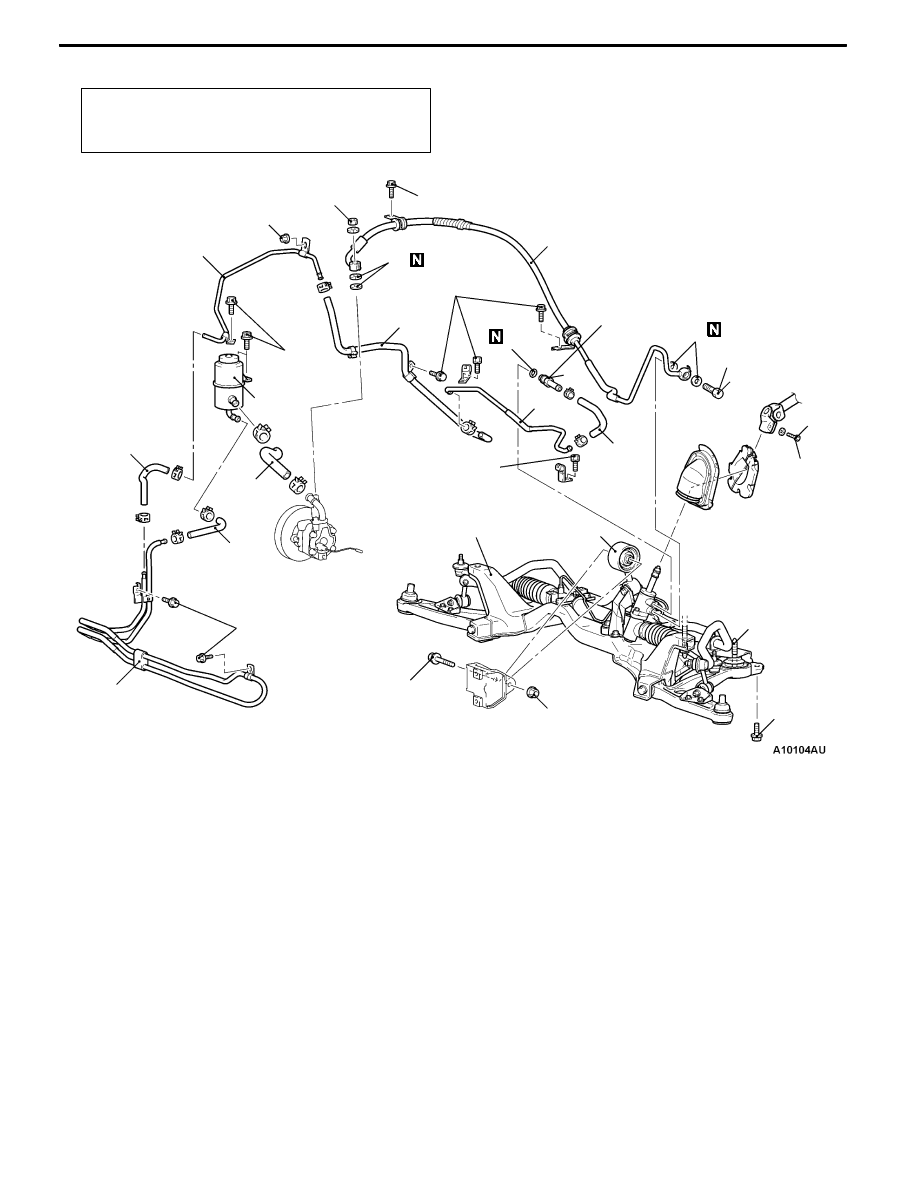
STEERING - Power Steering Oil Hoses
37A-31
<L.H. drive vehicles>
Pre-removal and Post-installation Operation
Power Steering Fluid Draining and Refilling (Refer to
P.37A
-9.)
12 ± 2 N·m
17
16
15
12
18 ± 3 N·m
Crossmember
1
57 ± 7 N·m
9
8
4
7
3
2
5
12 ± 2 N·m
15 ± 3 N·m
18 ± 2 N·m
12 ± 2 N·m
49 ± 10 N·m
52 ± 7 N·m*
12 ± 2 N·m
6
10
11
167 ± 10 N·m
14
13
18
12 ± 2 N·m
12 ± 2 N·m
Removal steps
1. Oil reservoir
"
BA 2. Suction hose
3. Return hose
4. Return hose
5. Return tube
D
Strut tower bar (Refer to GROUP 42.)
6. Return hose
D
Clock spring (Refer to GROUP 52B.)
D
Crossmember bar
(Refer to GROUP 33A.)
D
Center member (Refer to GROUP 32.)
D
Front exhaust pipe
(Refer to GROUP 15.)
7. Steering gear and joint connecting
bolt
8. Rear roll stopper connecting bolt
9. Rear roll stopper
(Refer to GROUP 32.)
A
A"
10. Eye bolt
11. Gasket
"
BA 12. Pressure hose assembly
"
AA 13. O ring
14. Return hose
15. Return tube
A
A"
16. Return tube
17. O ring
D
Front bumper (Refer to GROUP 51.)
D
Intercooler (Refer to GROUP 15.)
18. Cooler tube assembly