Mitsubishi Lancer Evolution 7. Manual - part 333
STEERING - Power Steering Gear Box and Linkage
37A-27
2. If the total rotation torque or torque fluctuation does not
meet the standard values, adjust by returning the rack
support cover within a range of 0 to 30_.
Caution
(1) Adjust around the maximum limit of the standard
values.
(2) See that no ratcheting or catching are present
when operating the rack towards the shaft
direction.
(3) Measure the total pinion torque through the whole
stroke of the rack.
3. If the adjustment is impossible in the given range, check
the components of the rack support cover, and replace
if necessary.
"
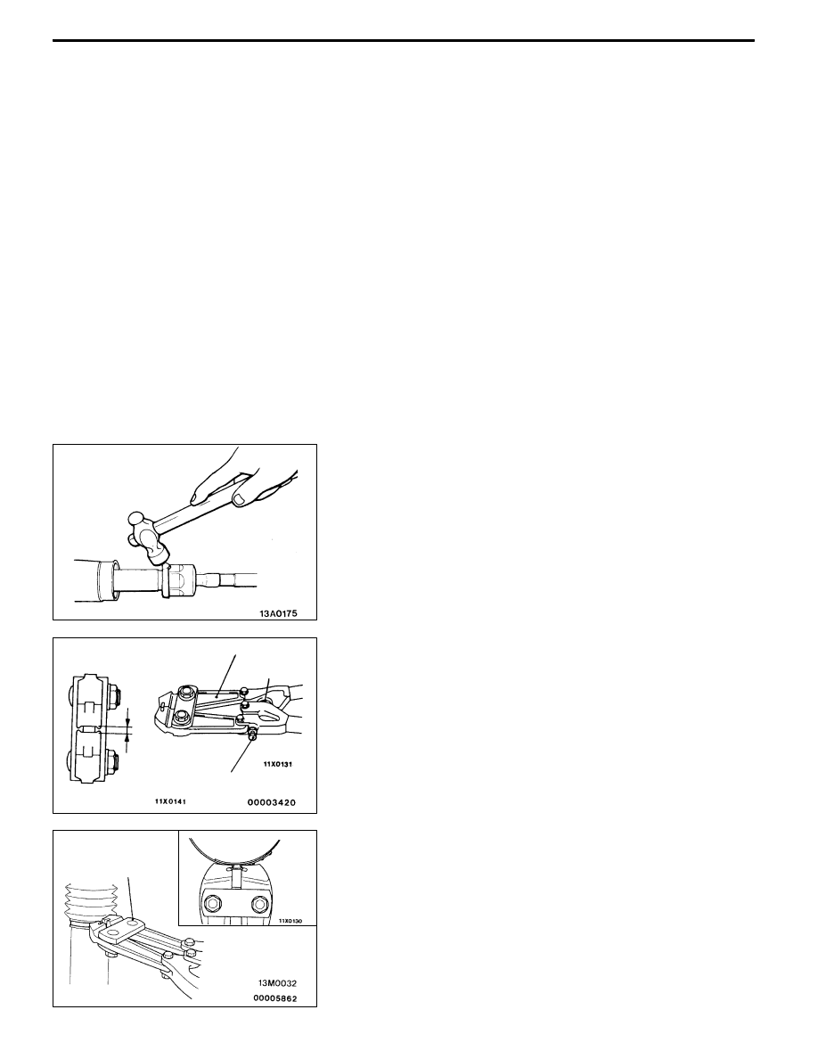
LA TAB WASHER/TIE ROD INSTALLATION
After installing the tie rod to the rack, fold the tab washer
end (2 locations) to the tie rod notch.
"
MABELLOWS BAND INSTALLATION
1. Turn the adjusting bolt of the special tool to adjust the
opening dimension (W) to the standard value.
Standard value (W): 2.9 mm
<When more than 2.9 mm>
Screw in the adjusting bolt.
<When less than 2.9 mm>
Loosen the adjusting bolt.
NOTE
(1) The dimension (W) is adjusted by about 0.7 mm per
one turn.
(2) Do not turn the adjusting bolt more than one turn.
2. Use the special tool to crimp the bellows band.
Caution
(1) Hold the rack housing, and use the special tool
to crimp the bellows band securely.
(2) Crimp the bellows band until the special tool
touches the stopper.
MB991561
Stopper
Adjusting bolt
W
MB991561