Mitsubishi Lancer Evolution 7. Manual - part 328


  Index      Mitsubishi     Mitsubishi Lancer Evolution 7 - service repair manual


Search            


Content   ..  326  327  328  329   ..


Mitsubishi Lancer Evolution 7. Manual - part 328


STEERING -

On-vehicle Service

37A-7

ON-VEHICLE SERVICE

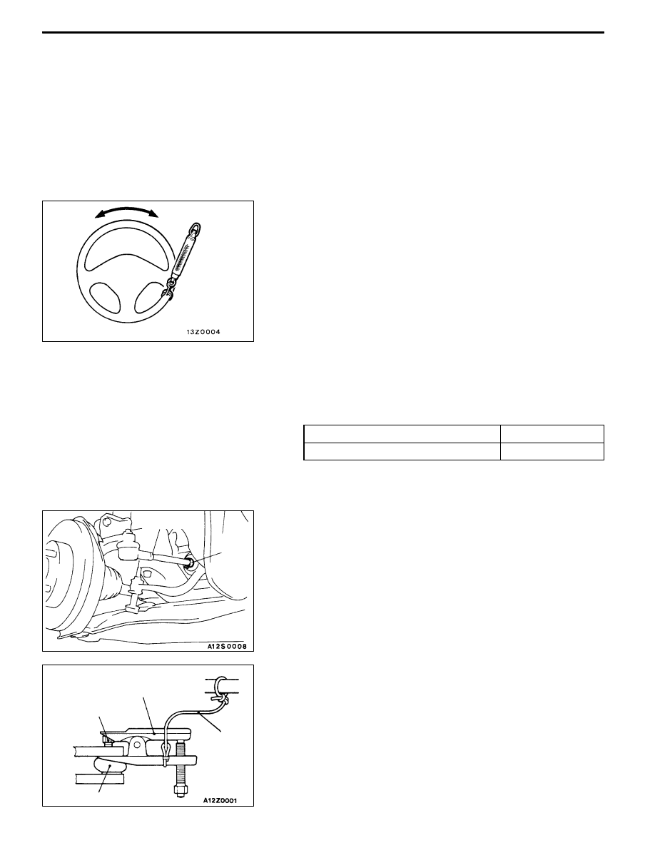
STEERING WHEEL FREE PLAY CHECK

1. With engine running (hydraulic operation), set front wheels

straight ahead.

2. Measure the play on steering wheel circumference before

wheels start to move when slightly moving steering wheel

in both directions.
Limit: 30 mm or less

3. When play exceeds the limit, check for play on steering

shaft connection and steering linkage. Correct or replace.

4. If the free play still exceeds the limit value, set steering

wheel straight ahead with engine stopped. Load 5 N

towards steering wheel circumference and check play.
Standard value: 0 - 10 mm

5. If the play exceeds the standard value, remove steering

gear box and check total pinion torque. (Refer to

P.37A-17.)

STEERING ANGLE CHECK

1. Locate front wheels on turning radius gauge and measure

steering angle.
Standard value:

Inner wheel

31_45’ ± 1_30’

Outer wheel<For reference>

27_15’

2. When the angle is not within the standard value, the

toe-in is probably incorrect. Adjust the toe-in.
Standard value: 0 ± 2 mm

Adjust the toe-in by undoing the clip and lock nut, and

turning the left and right tie rod turnbuckles by the same

amount (in opposite directions).

3. Recheck the steering angle.

TIE ROD END BALL JOINT TURNING TORQUE

CHECK

1. Disconnect tie rod and knuckle with special tool.

Caution

(1) Loosen the nut of the special tool, but do not

remove it. If it is removed, the ball joint thread

may be damaged.

(2) Tie the special tool with a cord so as not to fall

off.

Clip

Lock nut

Cord

Ball joint

Nut

MB990635,

MB991113 or

MB991406

STEERING -

On-vehicle Service

37A-8

2. Move ball joint stud several times and install nut on stud.

Measure ball joint turning torque with special tool.
Standard value: 1.0 - 3.0 N·m

3. When the turning torque exceeds the standard value,

replace tie rod end.

4. When the turning torque is under the standard value,

check ball joint for end play or ratcheting. If none of these,

the joint is still serviceable.

STATIONARY STEERING EFFORT CHECK

1. With the vehicle stopped on a flat, paved surface, turn

the steering wheel to the straight ahead position.

2. Start the engine and set it to 1,000±100 r/min.
3. Attach a spring balance to the outer circumference of

the steering wheel and measure the steering force

required to turn the steering wheel from the straight ahead

position to the left and right (within a range of 0.9 turns).

Also check to be sure that there is no significant fluctuation

of the required steering force.
Standard value:

Steering effort

32 N or less

Fluctuation allowance

6.0 N or less

4. If the standard values are not met, check and adjust

the related parts.

CHECKING STEERING WHEEL RETURN TO

CENTRE

To make this test, conduct a road test and check as follows.

1. Make both gradual and sudden turns and check the

steering “feeling” to be sure that there is not difference

in the steering force required and the wheel return between

left and right turns.

2. At a speed of 35 km/h, turn the steering wheel 90_ and

release the steering wheel after 1 or 2 seconds. If the

steering wheel then returns 70_ or more, the return can

be judged to be satisfactory.
NOTE

There will be a momentary feeling or “heaviness” when

the wheel is turned quickly, but this is not abnormal. (This

is because the oil pump discharge amount is especially

apt to be insufficient during idling.)

DRIVE BELT TENSION CHECK

Refer to GROUP 11A - On-vehicle Service.

MB990326

70_

70_

STEERING -

On-vehicle Service

37A-9

POWER STEERING FLUID LEVEL CHECK

1. Park the vehicle on a flat, level surface, start the engine,

and then turn the steering wheel several times to raise

the temperature of the fluid to approximately 50 - 60_C.

2. With the engine running, turn the wheel all the way to

the left and right several times.

3. Check the fluid in the oil reservoir for foaming or milkiness.

Check the difference of the fluid level when the engine

is stopped, and while it is running. If the change of the

fluid level is 5 mm or more, air bleeding should be done.

POWER STEERING FLUID REPLACEMENT

1. Raise the front wheels on a jack, and then support them

with rigid racks.

2. Disconnect the return hose connection.

3. Connect a vinyl hose to the return hose, and drain the

oil into a container.

4. Disconnect the ignition coil connectors. (Refer to

GROUP16 - Ignition System.)

5. While operating the starting motor intermittently, turn the

steering wheel all the way to the left and right several

times to drain all of the fluid.

6. Connect the return hoses securely, and then secure it

with the clip.

7. Fill the oil reservoir with specified fluid up to the lower

position of the filter, and then bleed air.
Specified fluid:

Automatic transmission fluid DEXRON II

Caution

Do not use ATF-SP II M and ATF-SP III.

POWER STEERING SYSTEM BLEEDING

1. Jack up the vehicle and support the front wheels with

rigid racks.

2. Disconnect the ignition coil connectors. (Refer to

GROUP16 - Ignition System.)

3. Cranking the engine with the starter several times

intermittently (during 15 to 20 seconds), turn the steering

wheel left and right fully five or six times.
Caution

(1) During the bleeding, refill the fluid so that the

level never falls below the lower position of the

filter.

(2) Be sure to bleed air only while cranking. If the

bleeding is done with the engine running, the air

will be broken up and absorbed into the fluid.

4. Connect the ignition coil connectors and idle the engine.

5. Turn the steering wheel left and right fully until no bubbles

comes out in the oil reservoir.

6. See that the fluid is not milky and that the fluid level

is up to the specified position on the level gauge.

7. See that the fluid level changes little when the steering

wheel is turned left and right.

8. Check difference in fluid levels between the engine

stopped and running.

Fluid level change: Within 5 mm

Whileengine

running

Whileengine

stopped

Return hose

Vinyl hose

STEERING -

On-vehicle Service

37A-10

9. If the level changes more than 5 mm, the air is badly

bled. So, bleed air again.
Caution

(1) If the fluid level rises suddenly after the engine

is stopped, the bleeding is incomplete.

(2) Incomplete bleeding causes abnormal noises

from the pump and the flow-control valve. This

could lessen the life of the pump and the other

parts.

OIL PUMP PRESSURE TEST

1. Disconnect the pressure hose from the oil pump, and

then connect the special tools.

2. Bleed the air, and then turn the steering wheel several

times while the vehicle is not moving so that the

temperature of the fluid rises to approximately 50 - 60_C.

3. Start the engine and idle it at 1,000±100 r/min.

4. Fully close the shut-off valve of the pressure gauge and

measure the oil pump relief pressure to confirm that it

is within the standard value range.
Standard value: 8.4 - 9.0 MPa

5. If the standard value is not met, the oil pump is defective.

So, replace the oil pump. Then, measure oil pressure

again.

6. With the pressure gauge shut-off valve fully open, check

the hydraulic pressure in unladen condition.
Standard value: 0.2 - 0.8 MPa

7. If the standard value is not met, the oil line or steering

gear is probably defective. So, repair and measure oil

pressure again.

8. Turn the steering wheel fully either left or right and check

the retention hydraulic pressure.
Standard value: 8.4 - 9.0 MPa

9. If the pressure is below the standard value, disassemble

and reassemble the steering gear. If above, replace the

oil pump. Then, measure oil pressure again.

10. Remove the special tools, and tighten the pressure hose

to the specified torque.
Tightening torque: 18 ± 3 N·m

11. Bleed the system.

Fluid level change: Within 5 mm

Whileengine

running

Whileengine

stopped

Temperature

gauge

Pressure

gauge

(MB990662)

Shut-offvalve

Oil

pump

Oil reservoir

Adapter

(MB990994)

Adapter

(MB990993)


Content   ..  326  327  328  329   ..