Mitsubishi Lancer Evolution 7. Manual - part 322
ABS <4WD> -
On-vehicle Service
35B-27
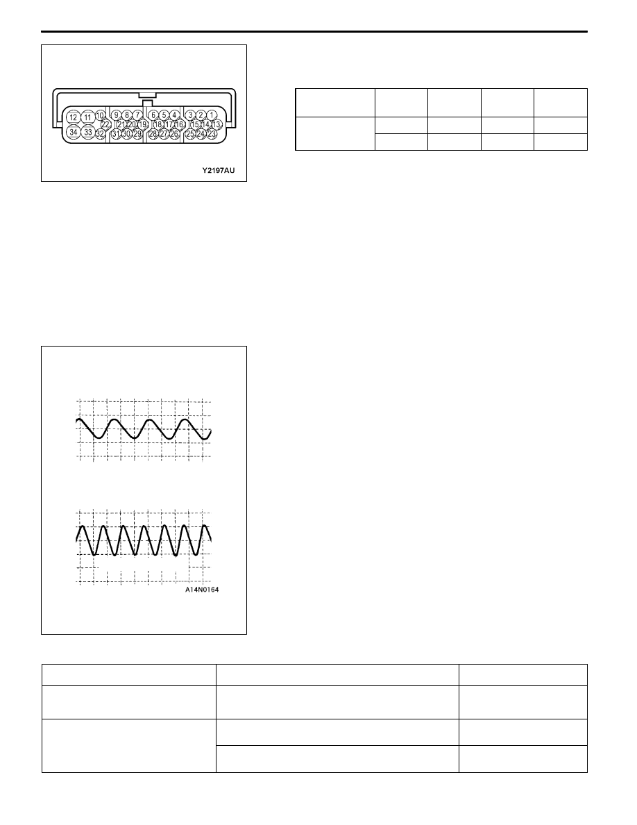
4. Rotate the wheel to be measured at approximately 1/2 - 1
rotation per second, and check the output voltage using a
circuit tester or an oscilloscope.
Wheel speed
sensor
Front
left
Front
right
Rear
left
Rear
right
Terminal No.
22
29
6
8
31
30
7
9
Output voltage
When measuring with a circuit tester:
42 mV or more
When measuring with an oscilloscope:
120 mV p-p or more
5. The followings are suspected if the output voltage is lower
than the value described above. Check the wheel speed
sensor, and replace if necessary.
D
Too large clearance between the pole piece of the
wheel speed sensor and ABS rotor
D
Faulty wheel speed sensor
Inspecting Waveforms With An Oscilloscope
Use the following method to observe the output voltage
waveform from each wheel speed sensor with an oscilloscope.
D
Start the engine, and rotate the front wheels by engaging
1st gear. Turn the rear wheels manually so that they
rotate at a constant speed.
NOTE
1. The waveform measurements can also be taken while
the vehicle is actually moving.
2. The output voltage will be small when the wheel speed
is low, and similarly it will be large when the wheel speed
is high.
Points In Waveform Measurement
Symptom
Probable causes
Remedy
Too small or zero waveform
amplitude
Faulty wheel speed sensor
Replace sensor
Waveform amplitude fluctuates
excessively (this is no problem if
Axle hub eccentric or with large runout
Replace hub
excessively (this is no problem if
the minimum amplitude is 100 mV
or more)
Faulty ABS-ECU earth
Repair
When turning by hand
When idling (5 - 6 km/h), 1st gear
10.0 ms/DIV 1 V/DIV