Mitsubishi Lancer Evolution 7. Manual - part 320


  Index      Mitsubishi     Mitsubishi Lancer Evolution 7 - service repair manual


Search            


Content   ..  318  319  320  321   ..


Mitsubishi Lancer Evolution 7. Manual - part 320


ABS <4WD> -

Troubleshooting

35B-19

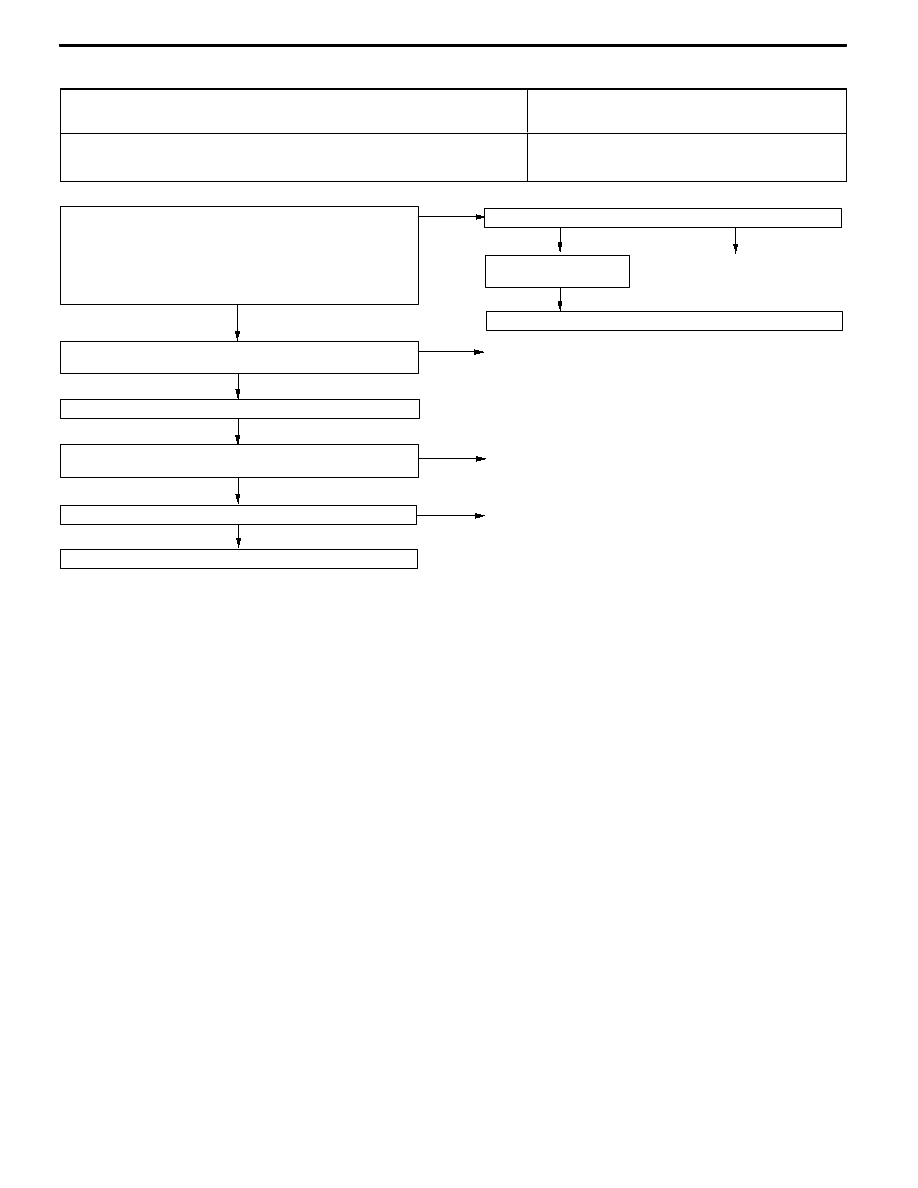
Inspection Procedure 5

In the inspection by MUT-II service data, the parking brake

switch is not turned ON or turn OFF.

Probable cause

ABS-ECU optimizes the ABS control when pulling the parking brake lever, parking

brake switch signal is used as support. If there is a fault in the parking brake switch

system, ABS control is not optimized.

D

Malfunction of parking brake switch

D

Malfunction of wiring harness or connector

D

Malfunction of hydraulic unit and ABS-ECU

OK

NG

NG

Check the harness wire.
D

Between parking brake switch and ABS-ECU

Replace the hydraulic unit and ABS-ECU.

OK

NG

OK

Check the trouble symptom.

Repair

NG

Repair

Check the following connectors: B-123, C-26, C-128 <R.H. drive

vehicles>, C-130 <L.H. drive vehicles>, D-23

Measure at the ABS-ECU connector B-123.
D

Disconnect the connector, and measure at the harness side

connector.

D

Measure by pulling or releasing the parking brake lever.

D

Continuity between 1 and body earth

OK: Continuity <Pulling the lever>

OK: No continuity <Releasing the lever>

NG

Repair

NG

OK

Check the trouble

symptom.

Check the following connector: B-123

OK

Replace the parking brake switch. (Refer to GROUP 36.)

NG

Repair

Check the parking brake switch installation condition.

ABS <4WD> -

Troubleshooting

35B-20

Inspection Procedure 6

The neutral position learning of the steering wheel sensor

is not finished.

Probable cause

The diagnosis is difficult because it depends on driving condition and road surface,

if the diagnosis code displays the normal code, carry out the following check.

D

Equipment the odd diameter tyre

D

Malfunction of suspension

D

Malfunction of steering wheel sensor installation

D

Malfunction of stop lamp switch system

D

Malfunction of hydraulic unit and ABS-ECU

NG

NG

NG

NG

Check the harness wire, and repair if necessary.
D

Between battery and stop lamp switch

D

Between stop lamp switch and ABS-ECU

OK

Check the trouble

symptom.

OK

Check the following connectors: B-123, C-103, C-108, C-130,

C-135

OK

Check the stop lamp switch. (Refer to GROUP 35A - Brake Pedal.)

Check the stop lamp switch installation condition.

(Refer to GROUP 35A - On-vehicle Service.)

NO

Repair

OK

NG

Repair

OK

NG

Repair

Replace

NG

Replacethehydraulicunit

and ABS-ECU.

NG

Check the harness wire,

and repair if necessary.
D

Between stop lamp

switch and ABS-ECU

Repair

Check the trouble

symptom.

NG

Check the following

connectors:

C-108, C-130

Check the trouble

symptom.

OK

Check the following

connector: B-123

YES

Measure at the ABS-ECU connector B-123.
D

Disconnect the connector, and measure at the harness side

connector.

D

Stop lamp switch: ON

D

Voltage between 19 and body earth

OK: System voltage

Does the stop lamp turn on and off normally?

YES

Repair

NO

Is the odd diameter tire equipped?

YES

Repair

NO

Is the suspension abnormal?

NO

YES

When the steering wheel position is neutral, does the steering wheel

sensor (ST-N) turn ON in the MUT-II service data?

Check the steering wheel sensor and the steering wheel installation

condition.

ABS <4WD> -

Troubleshooting

35B-21

Inspection Procedure 7

Faulty ABS operation

Probable cause

This varies depending on the driving conditions and the road surface conditions, so

problem diagnosis is difficult. However, if a normal diagnosis code is displayed, carry

out the following inspection.

D

Improper installation of wheel speed sensor

D

Malfunction of wiring harness or connector

D

Malfunction of wheel speed sensor

D

Malfunction of ABS rotor

D

Foreign material adhering to wheel speed sensor

D

Malfunction of wheel bearing

D

Malfunction of hydraulic unit and ABS-ECU

OK

OK

Check the following connector: B-123

NG

Measure at the ABS-ECU connector B-123.
D

Disconnect the connector, and measure at the harness side

connector.

D

Resistances between 6 and 7, 8 and 9, 22 and 31, 29 and

30

OK: 1.24 - 1.64 kΩ

(The sensor harness and connector should be moved while

these inspections are carried out.)

NG

OK

Check the trouble symptom.

OK

NG

Repair

OK

Wheel bearing check (Refer to GROUP 26 and GROUP 27 -

On-vehicle Service.)

NG

Repair

OK

ABS rotor check (Refer to P.35B-34.)

NG

Repair

NG

Wheel speed sensor check (Refer to P.35B-34.)

NG

Replace the wheel speed sensor.

OK

Wheel speed sensor output voltage check (Refer to P.35B-26.)

OK

Hydraulic unit check (Refer to P.35B-28.)

Wheel speed sensor installation check

NG

Repair

Check the harness wire.
D

Between each wheel speed sensor and ABS-ECU

NG

Repair

NG

NG

Repair

OK

Check the following connectors: B-123, C-128 <R.H. drive

vehicles>, C-43

NG

Check the trouble symptom.

Repair

NG

OK

Check the harness wire.
D

Between 4WD-ECU and ABS-ECU

OK

Measure at the 4WD-ECU connector C-43. <ABS signal check>
D

Disconnect the connector, and measure at the harness side

connector.

D

Carry out the ABS signal of the actuator test from the ABS

menu of the MUT-II.

D

Voltage between 49 and body earth

OK: Less than 1.0V for initial 10 seconds, then system voltage

NG

ABS signal check
D

Display the ABS signal of the service data from ACD (4WD)

menu of MUT-II.

OK: Displays OFF

D

Brake in safety area, operate the ABS (possible to inspect

in first velocity of approx. 30km/h)

OK: Displays ON (in operating ABS)

NG

Check the trouble symptom.

Replace the hydraulic unit and ABS-ECU.

Check the following connectors:

A-03, A-37, A-43 <L.H. drive vehicles>, C-111, C-128, C-136 <R.H.

drive vehicles>, C-146, D-04, D-10, D-30

ABS <4WD> -

Troubleshooting

35B-22

DATA LIST REFERENCE TABLE

The following items can be read by the MUT-II from the ABS-ECU input data.

1. When the system is normal

Item No.

Check item

Checking requirements

Normal value

11

Front-right wheel speed sensor

Perform a test run

Vehicle speeds

displayed on the

12

Front-left wheel speed sensor

displayed on the

speedometer and

MUT II are identical

13

Rear-right wheel speed sensor

MUT-II are identical.

14

Rear-left wheel speed sensor

21

Power supply voltage

Ignition switch: ON

10 - 16 V

29

Parking brake switch

Pull the parking brake lever.

ON

Release the parking brake lever.

OFF

36

Stop lamp switch

Depress the brake pedal.

ON

Release the brake pedal.

OFF

37

Steering wheel sensor neutral

position learning

After driving straightly with vehicle speed more

than 10km/h

ON

Before driving with ignition switch ON

OFF

71

Lateral G sensor

When vehicle stops

2.4 - 2.6 V

When vehicle drives

1.0 - 4.0 V

74

Steering wheel sensor (ST-N)

Ignition switch: ON

Steering:

Neutral position and

position near by ±

360_

ON

Steering:

Except for above

OFF

75

Steering wheel sensor (ST-1)

Ignition switch: ON

Steering:

Turn laterally slowly

Display ON and OFF

alternately

76

Steering wheel sensor (ST-2)

Turn laterally slowly

alternately

86

Steering degree

Ignition switch: ON
Steering wheel sensor

t l

iti

l

i

Steering: Steer by

90_ to the right

+90_

g

neutral position learning

is finished (service data

N 37 di l

ON)

Steering: Neutral

OFF

(

No. 37 displays ON)

Steering: Steer by

90_ to the left

-90_

2. When the ABS-ECU shut off ABS operation
When the diagnosis system stops the ABS-ECU, the MUT-II display data will be unreliable.


Content   ..  318  319  320  321   ..