Mitsubishi Lancer Evolution 7. Manual - part 323
ABS <4WD> -
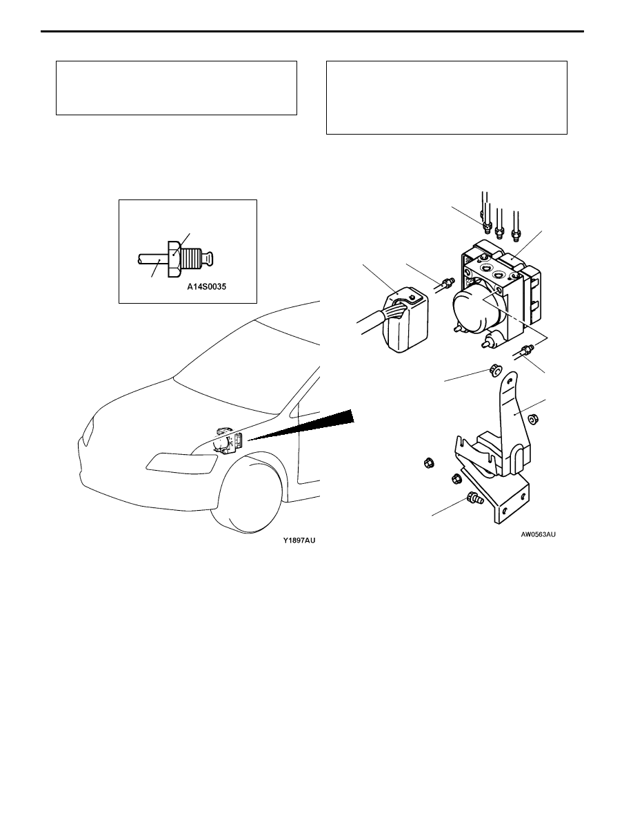
Hydraulic Unit and ABS-ECU
35B-31
<R.H. drive vehicles>
Pre-removal Operation
D
Strut Tower Bar Removal (Refer to GROUP 42.)
D
Brake Fluid Draining
D
Air Intake Hose and Air Cleaner Removal
Post-installation Operation
D
Brake Fluid Supplying and Brake Line Bleeding
(Refer to GROUP 35A - On-vehicle Service.)
D
Hydraulic Unit Check (Refer to P.35B-28.)
D
Air Intake Hose and Air Cleaner Installation
D
Strut Tower Bar Installation (Refer to GROUP 42.)
2
1
3
4
2
2
2
15 ± 2 N·m
25 ± 6 N·m
25 ± 6 N·m
Removal steps
A
A"
1. Harness connector
"
AA 2. Brake pipe connection
A
B"
3. Hydraulic unit and ABS-ECU
4. Hydraulic unit bracket assembly