Mitsubishi Lancer Evolution 7. Manual - part 306
REAR SUSPENSION -
Lower Arm Assembly/Toe Control Arm Assembly
34-13
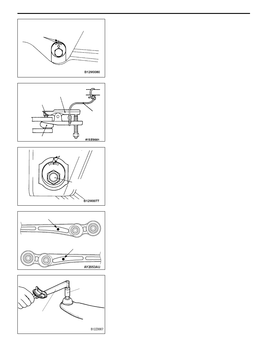
REMOVAL SERVICE POINTS
A
A" LOWER ARM ASSEMBLY MOUNTING BOLT
REMOVAL
Mark the mating marks on the lower arm and the decentering
cam bolt,then remove the lower arm and the decentering cam
bolt.
A
B" TOE CONTROL ARM ASSEMBLY AND KNUCKLE
DISCONNECTION
Caution
1. To prevent the ball joint thread from damage, only
loosen but do not remove the nut securing the upper
arm to the knuckle from the ball joint and use the
special tool.
2. The special tool should be suspended from a cord
to prevent it from being dropped.
A
C" TOE CONTROL ARM ASSEMBLY MOUNTING
BOLT REMOVAL
Mark the mating mark on the toe control arm and the
decentering cam bolt,then remove the toe control arm and the
decentering cam bolt.
INSTALLATION SERVICE POINTS
"
AA LOWER ARM ASSEMBLY INSTALLATION
Check the identification mark, install the lower arm assembly.
INSPECTION
TOE CONTROL ARM BALL JOINT ROTATION TORQUE
CHECK
1. After shaking the toe control arm ball joint stud several
times, use the special tool to measure the rotation torque
of the toe control arm ball joint.
Standard value: 0.5 - 2.5 N·m
2. When the measured value exceeds the standard value,
replace the toe control arm assembly.
Mating marks
Cord
Ball joint
Nut
MB991406,
MB990635 or
MB991113
Mating marks
Decentering
cam bolt
with red marking: RH side lower arm
assemblly
with countersunk ø10 mm: LH side lower arm
assemblly
MB990326
MB990968