Mitsubishi Lancer Evolution 7. Manual - part 305
REAR SUSPENSION -
Upper Arm Assembly
34-9
REMOVAL SERVICE POINTS
A
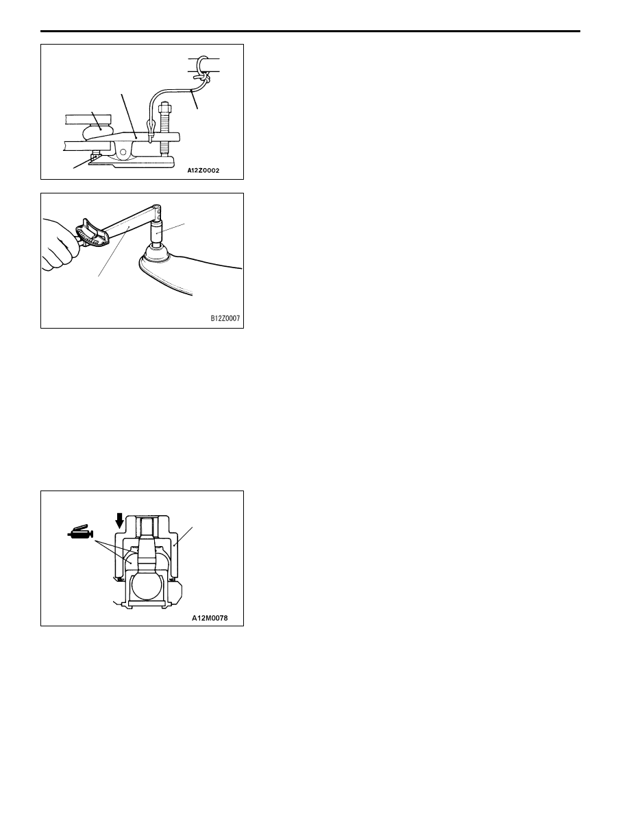
A" UPPER ARM BALL JOINT AND KNUCKLE
DISCONNECTION
Caution
1. To prevent the ball joint thread from damage, only
loosen but do not remove the nut securing the upper
arm to the knuckle from the ball joint and use the
special tool.
2. The special tool should be suspended from a cord
to prevent it from being dropped.
INSPECTION
UPPER ARM BALL JOINT ROTATION TORQUE CHECK
1. After shaking the upper arm ball joint stud several times,
use the special tool to measure the rotation torque of
the upper arm ball joint.
Standard value: 0.5 - 2.5 N·m
2. When the measured value exceeds the standard value,
replace the upper arm assembly.
3. When the measured value is lower than the standard
value, check that the upper arm ball joint turns smoothly
without excessive play. If there is no excessive play, the
ball joint can be reused.
UPPER ARM BALL JOINT DUST COVER CHECK
1. Check the dust cover for cracks or damage by pushing
it with finger.
2. If the dust cover is cracked or damaged, replace the
upper arm assembly.
NOTE
Cracks or damage of the dust cover may cause damage
of the ball joint. When it is damaged during service work,
replace the dust cover.
UPPER ARM BALL JOINT DUST COVER
REPLACEMENT
Only when the dust cover is damaged accidentally during
service work, replace the dust cover as follows:
1. Remove the dust cover.
2. Fill the multipurpose grease in the dust cover and lublicate
the lip. (Amount of filling grease in the dust
cover:approx.7g)
3. Using the special tool, punch the dust cover until it contacts
the snap ring.
4. Press the dust cover with your finger to check that there are
no cracks or damage in the dust cover.
Cord
Ball joint
Nut
MB991406,
MB990635 or
MB991113
MB990326
MB990968
MB990800