Mitsubishi Lancer Evolution 7. Manual - part 301
FRONT SUSPENSION -
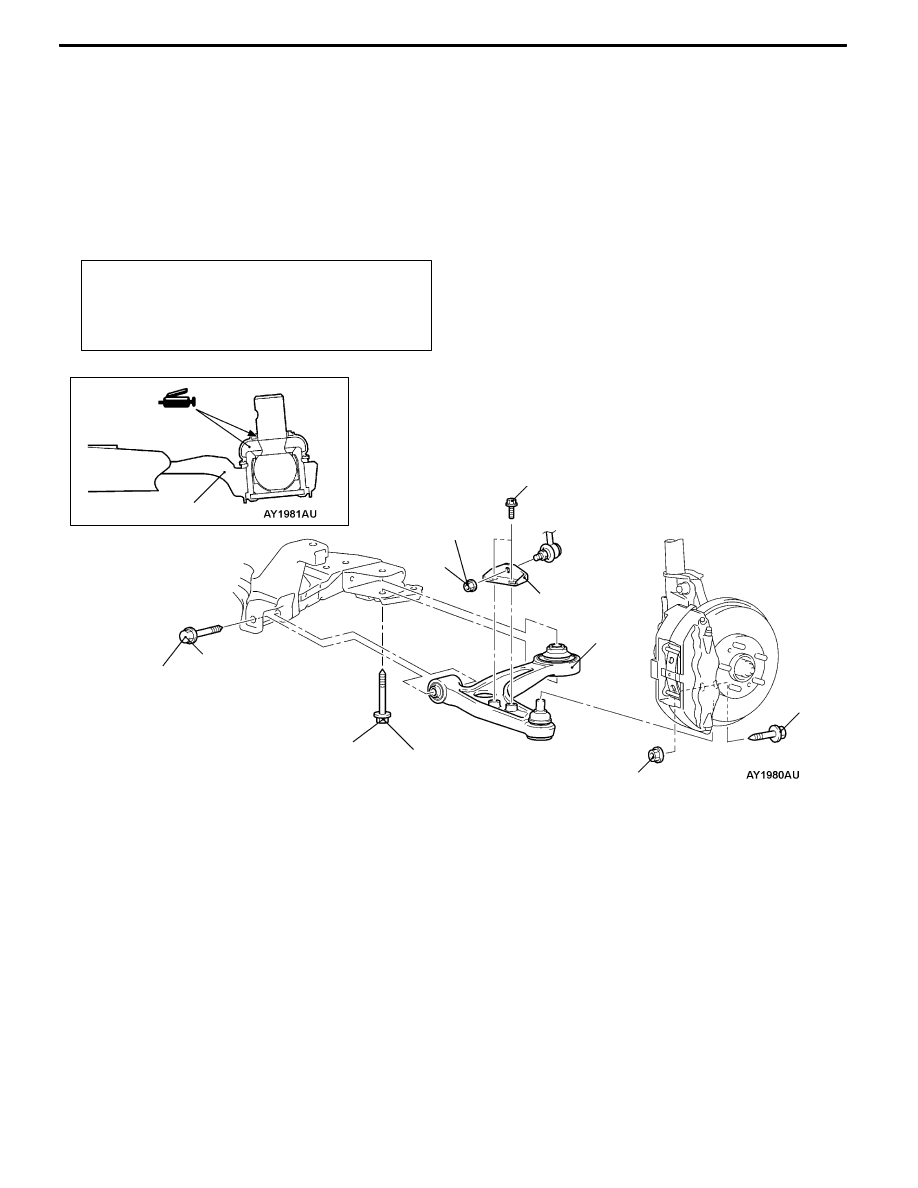
Lower Arm Assembly
33A-9
LOWER ARM ASSEMBLY
REMOVAL AND INSTALLATION
Caution
1. If the vehicle is equipped with the Brembo disc brake, during maintenance, take care not to
contact the parts or tools to the caliper because the paint of caliper will be scratched. And
if there is brake fluid on the caliper, wipe out quickly.
2. *: To prevent bushings from breakage, the parts indicated by * should be temporarily tightened,
and then fully tightened with the vehicle on the ground in the unladen condition.
Post-installation Operation
D
Check the dust cover for cracks or damage by
pushing it with finger.
D
Wheel alignment check and adjustment
(Refer to P.33A-4.)
7
2
5
186 ± 10 N·m*
3
167 ± 9 N·m
5
1
3
4
108 ± 10 N·m
39 ± 5 N·m
39 ± 5 N·m
Removal steps
1. Stabilizer link nut
2. Lower arm and knuckle connection
A
A"
3. Lower arm and crossmember
connection
4. Stabilizer bracket
5. Lower arm assembly