Mitsubishi Lancer Evolution 7. Manual - part 236
ENGINE AND EMISSION CONTROL -
Emission Control System
17-5
SERVICE SPECIFICATIONS
Items
Standard value
Purge control solenoid valve coil resistance (at 20_C) Ω
30 - 34
EGR control solenoid valve coil resistance (at 20_C) Ω
29 - 35
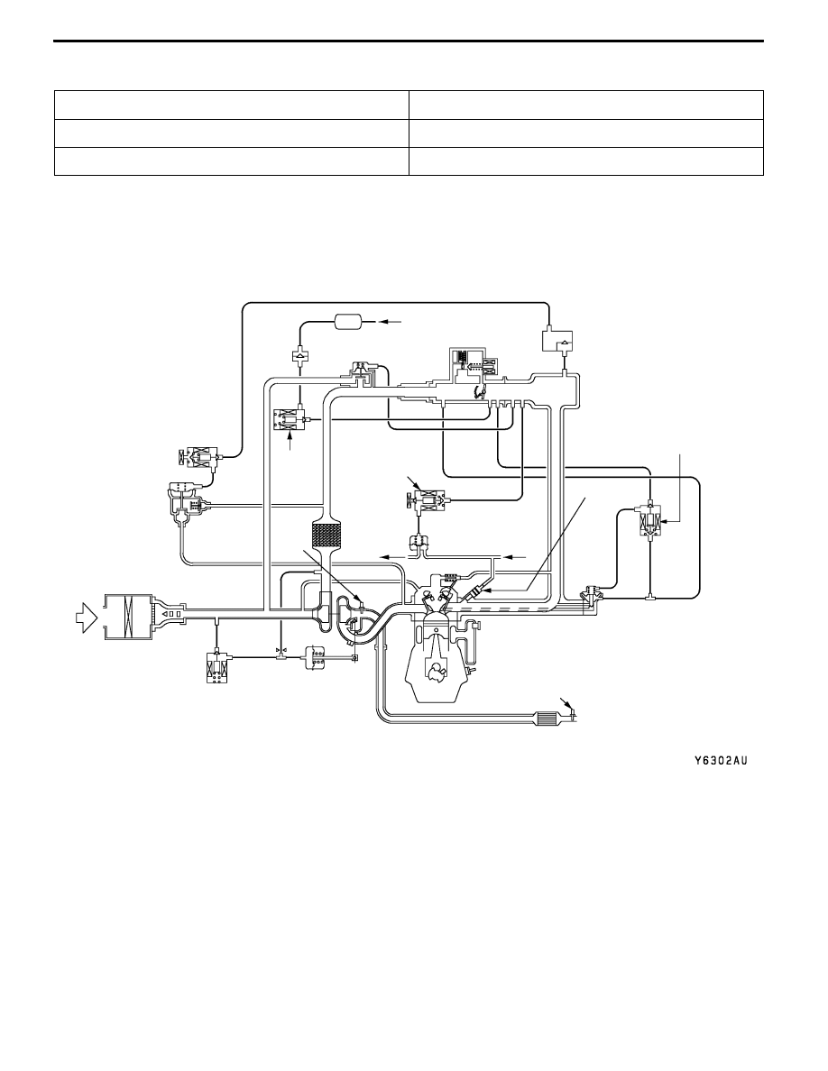
VACUUM HOSE
VACUUM HOSE PIPING DIAGRAM
Fuel
pressure
control
solenoid
valve
Oxygen
sensor
(front)
Check
valve
Fuel
pressure
regulator
PCV valve
To
fuel tank
Oxygen sensor (rear)
From
fuel pump
Air
inlet
EGR control
solenoid valve
Purge
control
solenoid
valve
Canister
From
fuel tank
EGR
valve
Injector
Three-way
catalytic converter
A
P
E