Mitsubishi Lancer Evolution 7. Manual - part 234


  Index      Mitsubishi     Mitsubishi Lancer Evolution 7 - service repair manual


Search            


Content   ..  232  233  234  235   ..


Mitsubishi Lancer Evolution 7. Manual - part 234


ENGINE ELECTRICAL -

Ignition System

16-35

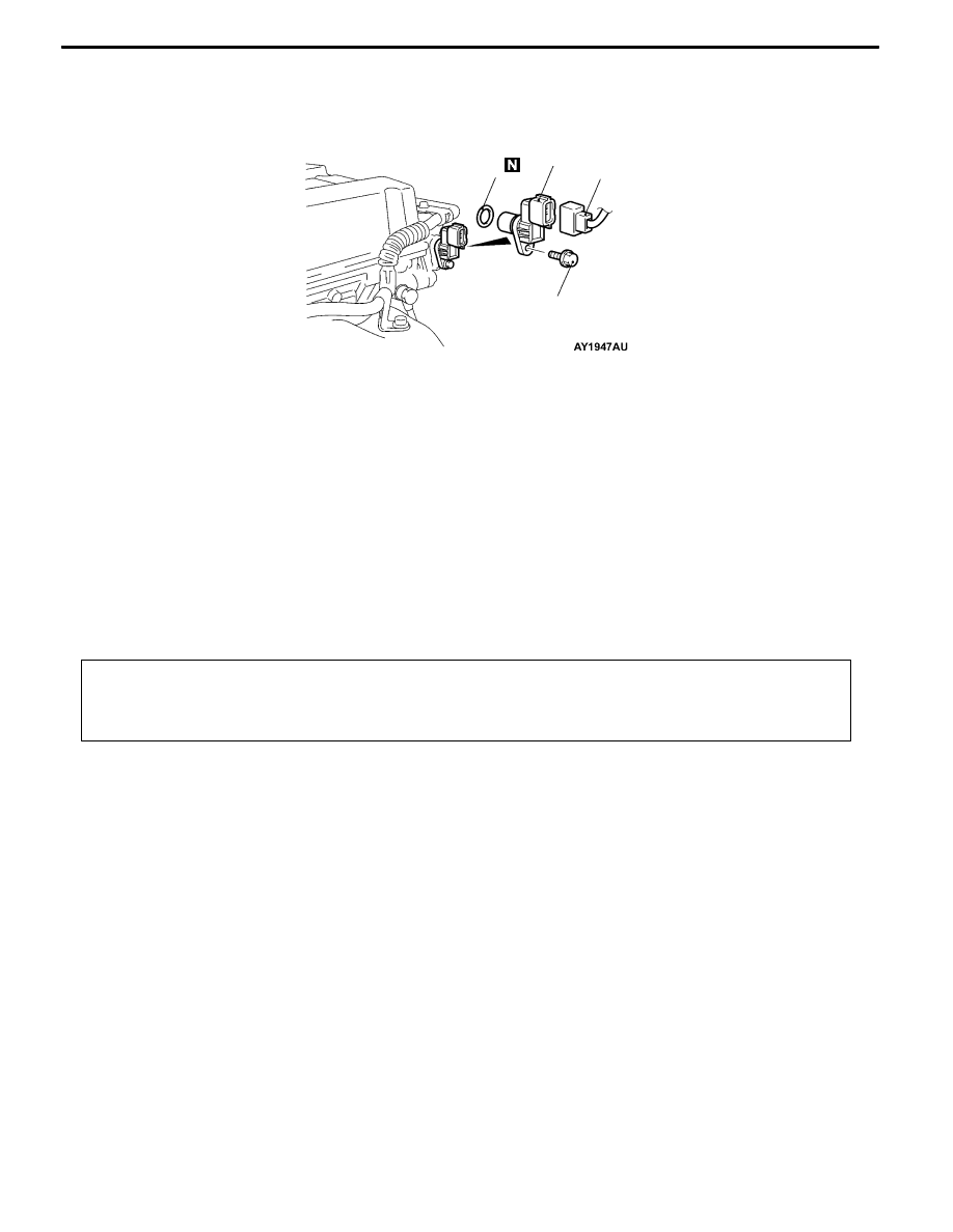
CAMSHAFT POSITION SENSOR

REMOVAL AND INSTALLATION

1

2

3

8.8 ± 1.0 N·m

Removal steps

1. Camshaft position sensor connector

2. Camshaft position sensor

3. O-ring

CRANK ANGLE SENSOR

REMOVAL AND INSTALLATION

Caution
If the vehicle is equipped with the Brembo disc brake, during maintenance, take care not to contact
the parts or tools to the caliper because the paint of caliper will be scratched.

Pre-removal and Post-installation Operation
D

Center Cover Removal and Installation (Refer to GROUP 11A - Camshaft and Camshaft Oil Seal.)

D

Timing Belt Removal and Installation (Refer to GROUP 11A.)

D

Reserve Tank Removal and Installation (Refer to GROUP 14 - Radiator.)

ENGINE ELECTRICAL -

Ignition System

16-36

1

2

3

8.8 ± 1.0 N·m

4

5

6

7

8.8 ± 1.0 N·m

49 ± 9 N·m

49 ± 9 N·m

40 ± 5 N·m

12 ± 2 N·m

22 ± 4 N·m

22 ± 4 N·m

12 ± 2 N·m

22 ± 4 N·m

Removal steps

1. Power steering oil pressure switch

connector

2. Heat protector

A

A"

3. Power steering oil pump, bracket and

oil reservoir assembly

4. Power steering oil pump bracket

5. Crank angle sensor connector

6. Crank angle sensor

7. Connector bracket

REMOVAL SERVICE POINT

A

APOWER STEERING OIL PUMP, BRACKET AND

OIL RESERVOIR ASSEMBLY REMOVAL

Remove the power steering oil pump, bracket and oil reservoir

assembly with the hose attached from the bracket.
NOTE

Tie the removed oil pump with a rope and set aside where

they cannot hinder the removal of the power steering oil pump

bracket.

ENGINE ELECTRICAL -

Ignition System

16-37

DETONATION SENSOR

REMOVAL AND INSTALLATION

Caution

Do not give any impact during removal and installation of detonation sensor.

Pre-removal and Post-installation Operation

Intake Manifold Stay Removal and Installation (Refer to GROUP 15 - Intake Manifold.)

1

2

23 ± 2 N·m

Removal steps

1. Detonation sensor connector

A

A" "AA 2. Detonation sensor

REMOVAL SERVICE POINT

A

ADETONATION SENSOR REMOVAL

INSTALLATION SERVICE POINT

"

ADETONATION SENSOR INSTALLATION

MD998773

NOTES


Content   ..  232  233  234  235   ..